Cryogenic container, superconductivity magnetic energy storage (SMES) system, and method for shielding a cryogenic fluid

a cryogenic fluid and magnetic energy storage technology, applied in the field of cryogenic containers, can solve the problems of large non-portable smes systems of the past, and hundreds of feet in diameter

Inactive Publication Date: 2006-03-30
EDEN ENERGY
View PDF23 Cites 14 Cited by
  • Summary
  • Abstract
  • Description
  • Claims
  • Application Information

AI Technical Summary

Benefits of technology

[0011] In the illustrative embodiment the inner vessel comprises a metal cylinder, and the superconducting layer covers either an inner surface (ID), or an outer surface (OD) of the inner vessel. Preferably, the superconducting layer comprises a low temperature superconductor material, such as magnesium diboride, a niobium alloy, a copper oxide or a BCS superconductor. The superconducting layer creates a magnetic field, which shields the cryogenic fluid from electromagnetic energy, reducing heat transfer from the environment, and maintaining the cryogenic fluid at low temperatures.
[0012] Heat transfer in the cryogenic container is affected by a number of factors, including, but not limited to, the infrared heating of the cold surfaces, conductive heat transfer by gas molecules from warm surfaces to cold surfaces, and conductive heat transfer through the support structure for the inner vessel. The magnetic field created by the superconducting layer reduces heat transfer due to infrared heating of the cold surfaces. The insulation in the annulus also reduces heat transfer from the environment to the cryogenic fluid.

Problems solved by technology

In general, these prior art SMES systems are large non-portable, devices which are hundreds of feet in diameter.

Method used


Image

  • Cryogenic container, superconductivity magnetic energy storage (SMES) system, and method for shielding a cryogenic fluid
  • Cryogenic container, superconductivity magnetic energy storage (SMES) system, and method for shielding a cryogenic fluid
  • Cryogenic container, superconductivity magnetic energy storage (SMES) system, and method for shielding a cryogenic fluid

Examples


Embodiment Construction

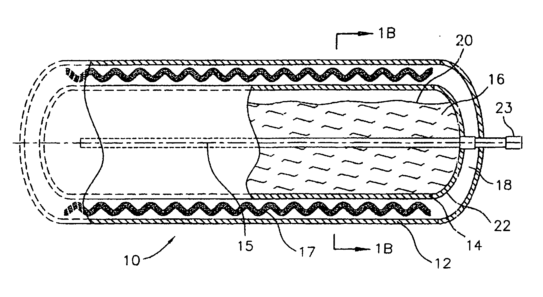
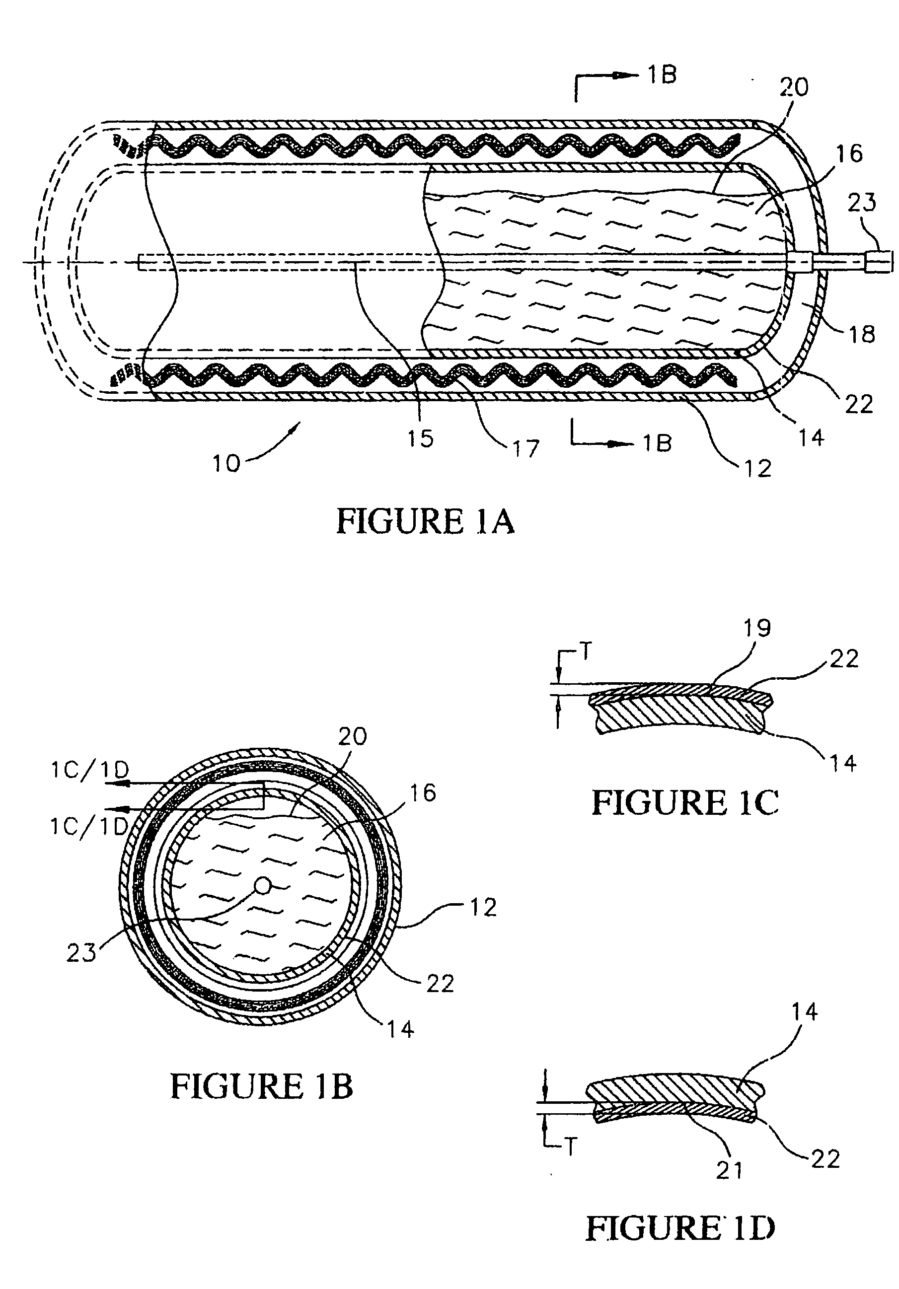
[0025] Referring to FIGS. 1A-1D, a cryogenic container 10 constructed in accordance with the invention is illustrated. The cryogenic container 10 includes an outer vessel 12, and an inner vessel 14 suspended within the outer vessel 12. The outer vessel 12 and the inner vessel 14 and are generally cylindrically shaped, fluid tight tanks having internal volumes selected as required. Rather than being cylindrical, the outer vessel 12 and the inner vessel 14 can have other shapes, such as cylindrical.

[0026] Both the outer vessel 12 and the inner vessel 14 can comprise any material commonly used in the construction of Dewar-type cryogenic tanks, such as steel, stainless steel, or non magnetic stainless steel. In addition, the inner vessel 14 can be suspended within the outer vessel 12 using any conventional structure, such as support rods or rings (not shown).

[0027] Since size of the cryogenic container 10 is a key to portability, it is preferred that for portable applications, the cry...


PUM

PropertyMeasurementUnit
volumeaaaaaaaaaa
diameteraaaaaaaaaa
diameteraaaaaaaaaa

Abstract

A cryogenic container includes an inner vessel for containing a cryogenic fluid, and an outer vessel for insulating the cryogenic fluid from the environment. The inner vessel includes a superconductive layer formed of a material having superconducting properties at the temperature of the cryogenic fluid. The superconductive layer forms a magnetic field around the cryogenic container, that repels electromagnetic energy, including thermal energy from the environment, keeping the cryogenic fluid at low temperatures. The cryogenic container has a portability and a volume that permits its' use in applications from handheld electronics to vehicles such as alternative fueled vehicles (AFVs). A SMES storage system includes the cryogenic container, and a SMES magnet suspended within the cryogenic fluid. The SMES storage system can also include a recharger and a cryocooler configured to recharge the cryogenic container with the cryogenic fluid.

Description

FIELD OF THE INVENTION [0001] This invention relates generally to cryogenic containers for storing cryogenic fluids. This invention also relates to superconductivity magnetic energy storage (SMES) using cryogenic containers. This invention also relates to methods for shielding cryogenic fluids from thermal energy. BACKGROUND OF THE INVENTION [0002] Cryogenic containers, such as dewar type containers and cryogenic tanks, are used to store cryogenic fluids such as liquid nitrogen, oxygen, hydrogen and neon. A conventional cryogenic container includes an inner tank configured to contain the cryogenic fluid, and an outer tank configured to provide a thermal barrier between the cryogenic fluid and the environment. In addition, the outer tank forms an annulus around the inner tank in which insulation, and in some systems a vacuum, is contained. The outer tank and the annulus are constructed to minimize the conduction of thermal energy from the environment to the cryogenic fluid. [0003] Cr...

Claims


Application Information

Patent Timeline
Patent Type & Authority Applications(United States)
IPC IPC(8): F17C3/08H01F6/06H01F6/00H01F7/02H01F36/00F17C13/00H01L39/24
CPCF17C3/04F17C2203/014F17C6/00F17C13/02F17C2201/01F17C2201/0104F17C2201/032F17C2201/035F17C2201/054F17C2201/056F17C2203/015F17C2203/0304F17C2203/0391F17C2203/0629F17C2203/0639F17C2203/0641F17C2203/0643F17C2203/0687F17C2205/0352F17C2221/011F17C2221/012F17C2221/014F17C2223/0161F17C2223/033F17C2250/04F17C2260/033F17C2270/0171F17C2270/0178H01F6/00H01F6/04H01F27/367Y02E60/321Y10S505/898Y10S505/875F17C3/08H01F27/36Y02E60/32H01F27/363
Inventor EGAN, GREGORY J.
Owner EDEN ENERGY
Why Eureka
Try Eureka