Honeycomb structure body

a technology of honeycomb and structure body, applied in the direction of metal/metal-oxide/metal-hydroxide catalyst, machine/engine, chemical/physical process, etc., can solve the problems of abnormal back pressure of the internal combustion engine, process disadvantage, and failure to apply catalyst and the lik

Inactive Publication Date: 2006-04-06
IBIDEN CO LTD
View PDF49 Cites 124 Cited by
  • Summary
  • Abstract
  • Description
  • Claims
  • Application Information

AI Technical Summary

Benefits of technology

[0028] The present invention has been devised so as to solve the above-mentioned problems, and its object is to provide a honeycomb structural body which makes it possible to clearly distinguish a side in whic...

Problems solved by technology

In the case where the honeycomb filter for purifying exhaust gases and the catalyst supporting member are manufactured through such a method, however, protruded portions and recessed portions (irregularities) of the porous ceramic member tend to appear on each of the end faces of the honeycomb filter for purifying exhaust gases or the like, due to shrinkage errors of the porous ceramic members in the manufacturing processes, positional deviations that occur upon stacking the ceramic laminated members, warps that occur in the porous ceramic members and the like.
Furthermore, in general, a honeycomb filter for purifying exhaust gases is inserted, for use, into a pipe that forms an exhaust passage in an internal combustion engine and, as described above, in the case where irregularities are formed on the end faces of the honeycomb filter for purifying exhaust gases, upon insertion into the pipe, the honeycomb filter for purifying exhaust gases tends to be inserted diagonally to cause problems after a long-term use.
Moreover, in the case where the pipe has a taper-shaped narrowed portion, the end of the honeycomb filter for purifying exhaust gases tends to collide with this potion to cause damages.
Such flattening processes to be applied to the two ends of a honeycomb filter for purifying exhaust gases are effective so as to solve the above-mentioned problems; however, these proc...

Method used


Image

  • Honeycomb structure body
  • Honeycomb structure body
  • Honeycomb structure body

Examples


example 1

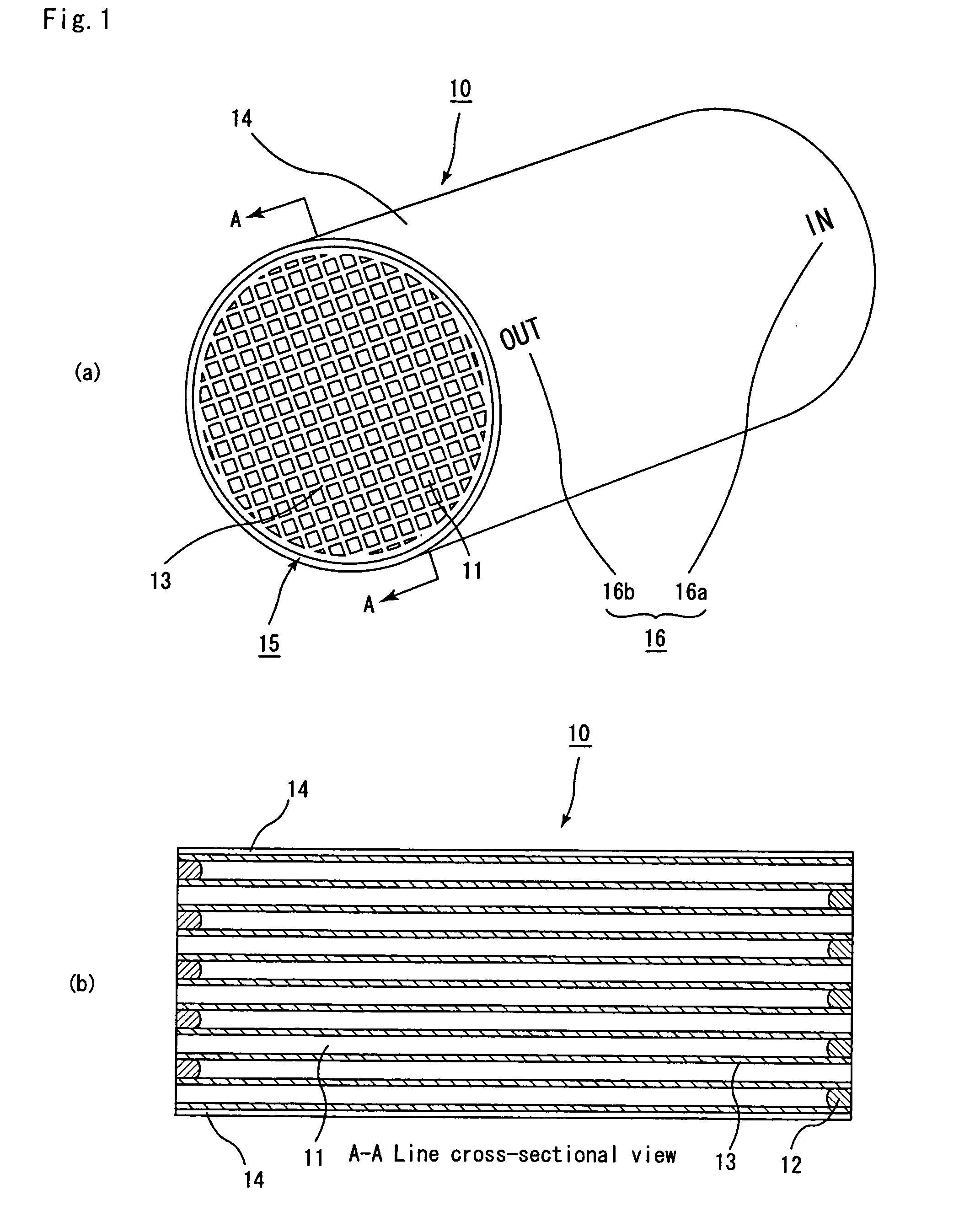
[0217] (1) Powder of α-type silicon carbide having an average particle size of 10 μm (60% by weight) and powder of β-type silicon carbide having an average particle size of 0.5 μm (40% by weight) were wet-mixed, and to 100 parts by weight of the resulting mixture were added and kneaded 5 parts by weight of an organic binder (methyl cellulose) and 10 parts by weight of water to prepare a kneaded matter. After a slight amount of a plasticizer and a lubricant had been added to the kneaded matter and this had been further kneaded, the resulting kneaded matter was extrusion-molded so that a raw molded product was manufactured.

[0218] Next, the above-mentioned raw molded product was dried by using a microwave drier, and predetermined through holes were then filled with a paste having the same composition as the raw molded product, and after having been again dried by using a drier, this was degreased at 400° C., and sintered at 2200° C. in a normal-pressure argon atmosphere for 3 hours to...

example 2

[0226] The same processes as Example 1 were carried out except that upon forming the ceramic laminated body, porous ceramic members were stacked with one end of each ceramic member being aligned and that process (3) of Example 1 was not carried out so that a honeycomb structural body was manufactured.

[0227] Here, the end face on the side at which the porous ceramic members had been stacked with aligned end face had a flatness of 1.0 mm, while the end face on the other side had a flatness of 2.5 mm. Moreover, in the present example, a character indicating “Face treated by flattening treatment” was displayed on the end face on the side in which at which the porous ceramic members were stacked with aligned end face.

[0228] Here, ten of these honeycomb structural bodies were prepared.


PUM

PropertyMeasurementUnit
Lengthaaaaaaaaaa
Diameteraaaaaaaaaa
Ratioaaaaaaaaaa

Abstract

An object of the present invention is to provide a honeycomb structural body which is inserted, for use, into a pipe forming an exhaust passage of an internal combustion engine, and makes it possible to clearly distinguish an exhaust gas flow-in side and an exhaust gas flow-out side. The present invention is directed to a columnar honeycomb structural body comprising porous ceramics each including a number of through holes that are placed in parallel with one another in the length direction with a wall portion interposed therebetween, wherein information regarding the honeycomb structural body is displayed on a circumferential surface and/or an end face thereof.

Description

CROSS REFERENCE TO RELATED APPLICATION [0001] This application claims benefit of priority to Japanese Patent Application No. 2003-128388, filed on May 6, 2003, the contents of which are incorporated by reference herein. TECHNICAL FIELD [0002] The present invention relates to a honeycomb structural body that is used as a filter and the like for purifying exhaust gases discharged from an internal combustion engine such as a diesel engine or the like. BACKGROUND ART [0003] There have been proposed various honeycomb filters for purifying exhaust gases and catalyst supporting members, which are used for purifying exhaust gases discharged from internal combustion engines of vehicles such as buses, trucks and the like, and construction machines. [0004] Specifically, for example, a honeycomb filter for purifying exhaust gases as shown in FIG. 5 has been proposed. In the honeycomb filter for purifying exhaust gases shown in FIG. 5, a plurality of porous ceramic members 30 made of silicon car...

Claims


Application Information

Patent Timeline
IPC IPC(8): B01J21/04B01D46/00B01D46/24F01N3/022
CPCB01D46/009B01D46/2418B01D46/2459B01D46/2466B01D46/247C04B41/009C04B41/4572C04B41/53C04B41/81C04B41/91C04B2111/00793C04B2111/0081F01N3/0222F01N2260/24F01N2310/06F01N2330/06F01N2330/30F01N2330/34F01N2350/02F01N2450/28C04B41/4535C04B41/0036C04B35/00C04B35/565C04B38/0006Y02T10/20B28B23/0031Y02T10/12B01D46/2484B01D46/2478F01N3/022F01N3/02B01D39/20
Inventor YAMADA, KEIJI
Owner IBIDEN CO LTD
Why Eureka
Try Eureka