

System for producing alloy containing rare earth metal
a rare earth metal and alloy technology, applied in the direction of quenching devices, heat treatment equipment, manufacturing tools, etc., can solve the problems of reducing the cooling rate of alloy flakes, reducing the efficiency of thermal history control, and oxidizing the hot alloy flakes instantly, so as to reduce the fluctuation of the thermal history of alloys, prevent the oxidation of alloys, and facilitate the effect of thermal history control
- Summary
- Abstract
- Description
- Claims
- Application Information
AI Technical Summary
Benefits of technology
Problems solved by technology
Method used
Image

Examples
example 1
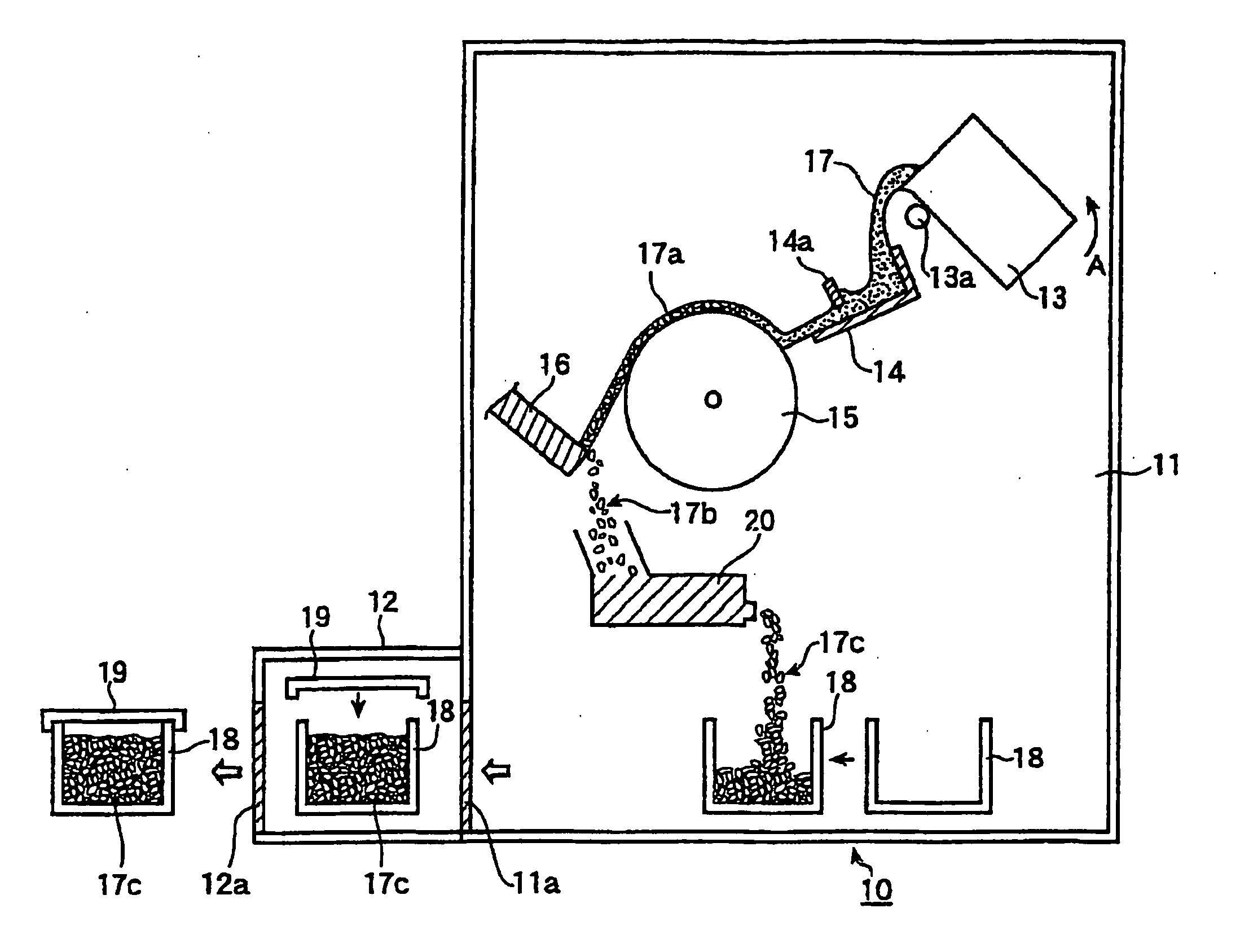
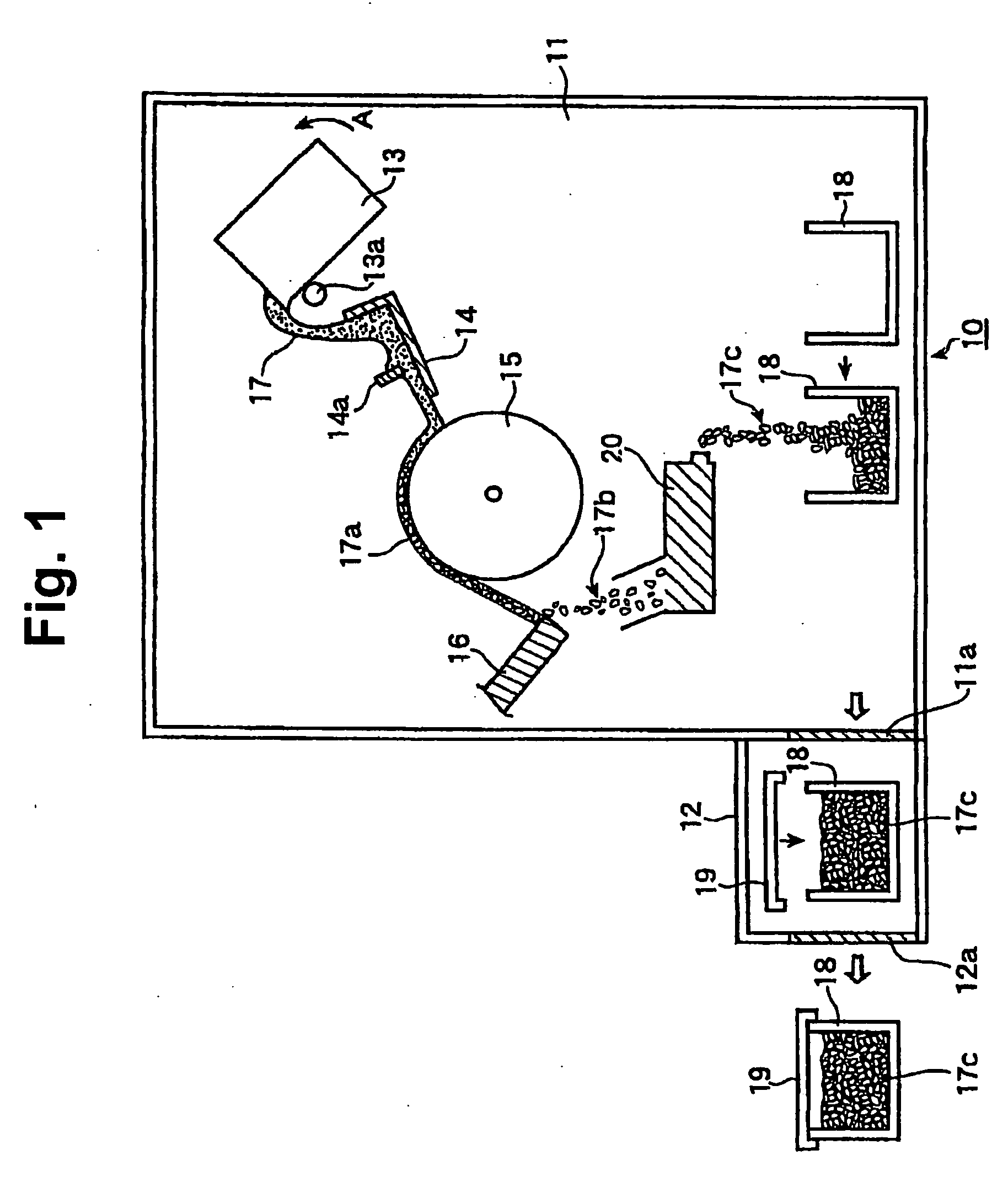
[0076] Alloy flakes were produced in the following process using the manufacturing system 10 shown in FIG. 1, wherein the device 20 was replaced with the device 50 shown in FIG. 5, and the cooling device 18 in the form of a container was replaced with a container having no cooling unit.
[0077] 32.8 mass % neodymium, 1.02 mass % boron, 0.28 mass % aluminum, and the balance of iron were weighed out so that the total weight was 500 kg, and melted in the vacuum melting furnace 13. The resulting alloy melt was discharged at 1430° C., fed onto the water-cooled copper roll 17a via the tundish 14, and continuously solidified. The surface velocity of the roll 17a was 1.2 m / sec. The temperature of the free surface of the alloy flakes solidified on the roll 17a was measured with an infrared thermometer at the location where the alloy flakes were separated from the roll, and found to be 880° C. It took 20 minutes from the start to the end of discharge of the alloy melt. The alloy flakes were cr...
PUM
| Property | Measurement | Unit |
|---|---|---|
| temperature | aaaaa | aaaaa |
| size | aaaaa | aaaaa |
| temperature | aaaaa | aaaaa |
Abstract
Description
Claims
Application Information