Regenerative relay system and regenerative relay apparatus

a relay and relay technology, applied in the direction of electromagnetic repeaters, instruments, coding, etc., can solve the problems of increasing the delay time of decoder and encoder, deterioration of light often, and increasing the coding gain, so as to increase the delay time and ensure good transmission quality

Inactive Publication Date: 2006-04-13
FUJITSU LTD
View PDF12 Cites 28 Cited by
  • Summary
  • Abstract
  • Description
  • Claims
  • Application Information

AI Technical Summary

Benefits of technology

[0014] Accordingly, it is a general object of the present invention to provide a novel and useful regenerative relay method and regenerative relay apparatus.
[0015] Another and more specific object of the present invention is to provide a regenerative relay method and regenerative relay apparatus whereby a necessary error correction is made without increasing delay time and good transmission quality can be secured.
[0022] According to the present invention, it is possible to make a necessary error correction without increasing delay time and secure good transmission quality.

Problems solved by technology

In this Wavelength Division Multiplex transmission, deterioration of light often happens due to mixing of noise by the optical amplifier, light dispersion or polarization by a long distance transmission, or the like.
Therefore, an error correction method wherein the number of the redundancy bits, the circuit size, the delay time, and the consumption of electric power are respectively small but the coding gain is large in demanded.
Therefore, the signal passes through the decoder even at a section where the number of errors is small so that signal delay by the decoder and the encoder is increased.

Method used


Image

  • Regenerative relay system and regenerative relay apparatus
  • Regenerative relay system and regenerative relay apparatus
  • Regenerative relay system and regenerative relay apparatus

Examples


first embodiment

of the Present Invention

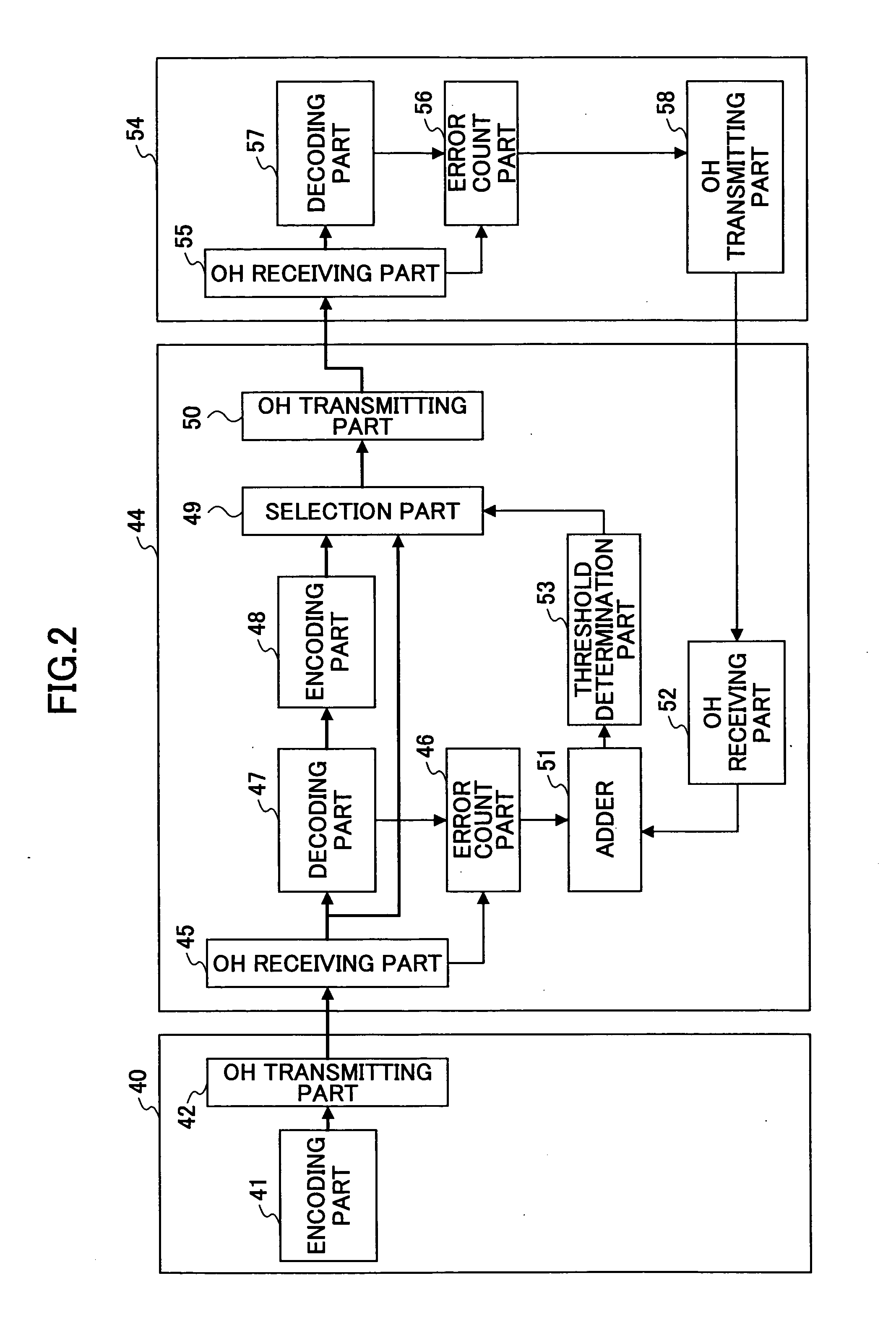
[0038]FIG. 2 is a structural view of a first embodiment of a relay method of the present invention. Referring to FIG. 2, an error correction code that is a redundancy bit for error correction is added to a signal in an encoding part 41 of a terminal apparatus 40. Overhead is added to the signal by an OH transmission part 42 so as to be transmitted to a regenerative relay apparatus 44 via a going-up (upstream) circuit.

[0039]FIG. 3 is a view showing an example of a frame format of a transmission signal. This shows the frame structure of a digital wrapper recommended by ITU-T G709. The transmission signal has a 4080×4 byte structure. This frame structure includes the overhead OH of 56 (=14×4) bytes, a data area OPUk of 15296 (=3824×4) bytes, and an error correction code FEC (Forward Error Correction) of 1024 byte.

[0040] An error detection code BIP 8 (Bit Interleaved Parity-level 8) is stored in the ninth column of the first line of the overhead. Backward error...

second embodiment

of the Present Invention

[0054]FIG. 5 is a structural view of a second embodiment of the relay method of the present invention. Referring to FIG. 5, an error correction code that is a redundancy bit for error correction is added to a signal in an encoding part 141 of a terminal apparatus 140. Overhead is added to the signal by an OH transmission part 142 so as to be transmitted to a regenerative relay apparatus 144 via a going-up (upstream) circuit.

[0055] In an OH receiving part 145 of the regenerative relay apparatus 144, the overhead of a receiving frame is terminated. Furthermore, data in the data area OPUk among the transmission signals of the frame format shown in FIG. 3 and the error correction code FEC are supplied to a decoding part 147 and a selection part 149.

[0056] The decoding part 147 decodes data by implementing the error correction of the data of the data area OPUk by using the error correction code FEC and implements timing regeneration, waveform shaping, and others...

third embodiment

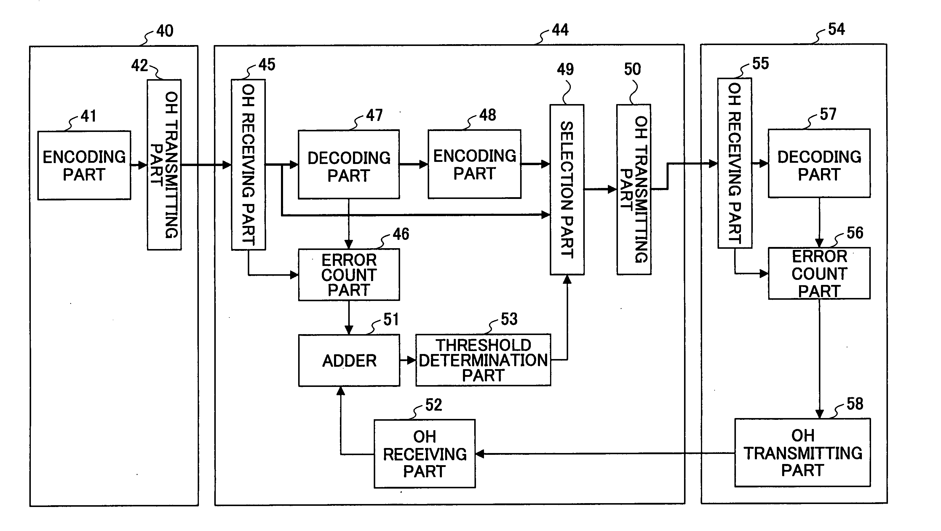
[0066]FIG. 6 is a structural view of a third embodiment of the relay method of the present invention. The difference between the first embodiment and the third embodiment is that, in the third embodiment, a threshold determination part is provided at a latter part terminal apparatus and a result of determination by the threshold determination part goes back to the regenerative relay apparatus so that control of the selection part is implemented.

[0067] Referring to FIG. 6, an error correction code that is a redundancy bit for error correction is added to a signal in an encoding part 241 of a terminal apparatus 240. Overhead is added to the signal by an OH transmission part 242 so as to be transmitted to a regenerative relay apparatus 244 via a going-up (upstream) circuit.

[0068] In an OH receiving part 245 of the regenerative relay apparatus 244, the overhead of a receiving frame shown in FIG. 3 is terminated, and error detection is done by using the error detection code BIP 8 in th...


PUM


Abstract

A regenerative relay method includes the steps of: i) calculating an error rate of a transmission path between the first half apparatus and a main apparatus; ii) calculating an error rate of a transmission path between the main apparatus and the latter apparatus; iii) adding the error rates; iv) selecting the error correction code and data before the error is corrected in the main apparatus so as to be supplied to the latter apparatus if the added error rates are lower than a designated error correction threshold; and v) selecting data after the error is corrected in the main apparatus and the other error correction code generated from the data so as to be supplied to the latter apparatus if the added error rates are higher than the designated error correction threshold.

Description

CROSS-REFERENCE TO RELATED APPLICATION [0001] This application is a U.S. continuation application filed under 35 USC 111(a) claiming benefit under 35 USC 120 and 365(c) of PCT application JP2003 / 009928, filed Aug. 5, 2003. The foregoing applications are hereby incorporated herein by reference.BACKGROUND OF THE INVENTION [0002] 1. Field of the Invention [0003] The present invention generally relates to regenerative relay methods and regenerative relay apparatuses, and more specifically, to a regenerative relay method and regenerative relay apparatus whereby, for example, a regenerative relay of a signal is implemented in an optical transmission system such as a Dense Wavelength Division Multiplexer (DWDM) system. [0004] 2. Description of the Related Art [0005] Recently and continuing, due to the increase of communications capability, a large amount of data can be transmitted by a transmission apparatus and long distance transmission of data can be done. In this state, an efficient op...

Claims


Application Information

Patent Timeline
Patent Type & Authority Applications(United States)
IPC IPC(8): G06F11/00H03M13/00H03M13/37H04B10/29H04L1/00H04L1/20
CPCH04L1/0045H04L1/0061H04L1/203H03M13/3715H03M13/3738H04L2001/0097
Inventor ONO, TAKESHI
Owner FUJITSU LTD
Why Eureka
Try Eureka