
Radiant tube heater assemblies

Inactive Publication Date: 2006-04-20
VANCAK JOHN
View PDF8 Cites 10 Cited by
  • Summary
  • Abstract
  • Description
  • Claims
  • Application Information

AI Technical Summary

Benefits of technology

[0008] An object of the present invention is to provide solutions to the above-identified problems in the form of a relatively simple, variable input, radiant tube heater, which is cost effective and easy to produce. The space requirements for such a system are relatively small, the components are readily available, and the system is easy to operate.
[0009] Another object of the invention is to provide a modular support system for radiant patio heaters which is easy to assemble on site, and which can readily be secured to existing patio surfaces using standard, readily available fasteners.
[0010] Yet another object of the invention is to provide a low voltage radiant heater, which is relatively safe to operate, easy to install thus requiring low skill, cost effective, and has decreased space requirements because there are fewer components inside of the heater burner box. Because of the low voltage there is no chance of electrocution, no need for special protected wire and installation can be effected without an electrician.

Problems solved by technology

In general, there are several drawbacks to currently available radiant tube heaters.
Another radiant heater problem involves outdoor patio heater systems.
Disadvantages of these types of structures are that a tube or post is required for every heater, taking up space on a patio.
In the case of an installation on an existing patio, the patio surface must be demolished to an extent sufficient to permit installation of underground fuel and / or electrical supply lines which is a costly undertaking.
Yet another problem with radiant heaters for patios is that the heat level or output of currently available patio heaters is controlled manually.

Method used


Image

  • Radiant tube heater assemblies
  • Radiant tube heater assemblies
  • Radiant tube heater assemblies

Examples


Embodiment Construction

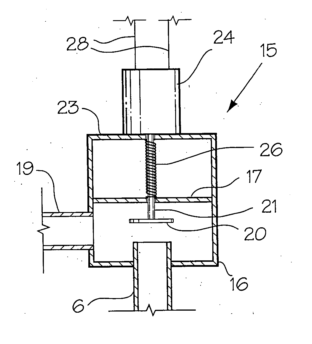
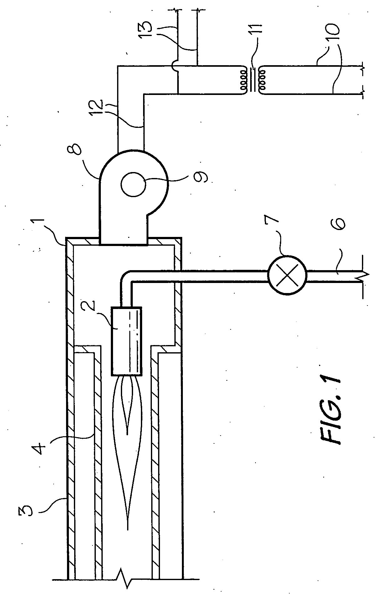
[0021] Referring to FIG. 1, a radiant heater in accordance with the invention includes a housing 1 carrying a burner 2, a reflector 3 and a burner tube 4. Gas is fed into the burner 2 via an inlet line 6 containing a valve 7. Combustion air is fed through one end of the housing 1 into the burner tube 4 by a blower 8. In accordance with a first aspect of the present invention, the motor 9 of the blower 8 is a 24 volt motor. High voltage is fed via lines 10 from a source thereof to a transformer 11, which is mounted on a wall or other location remote from the radiant heater. The transformer 11 is connected to the blower motor by lines 12. Taps 13 can draw low voltage from the lines 12 for feeding current to other low voltage components of a burner assembly.

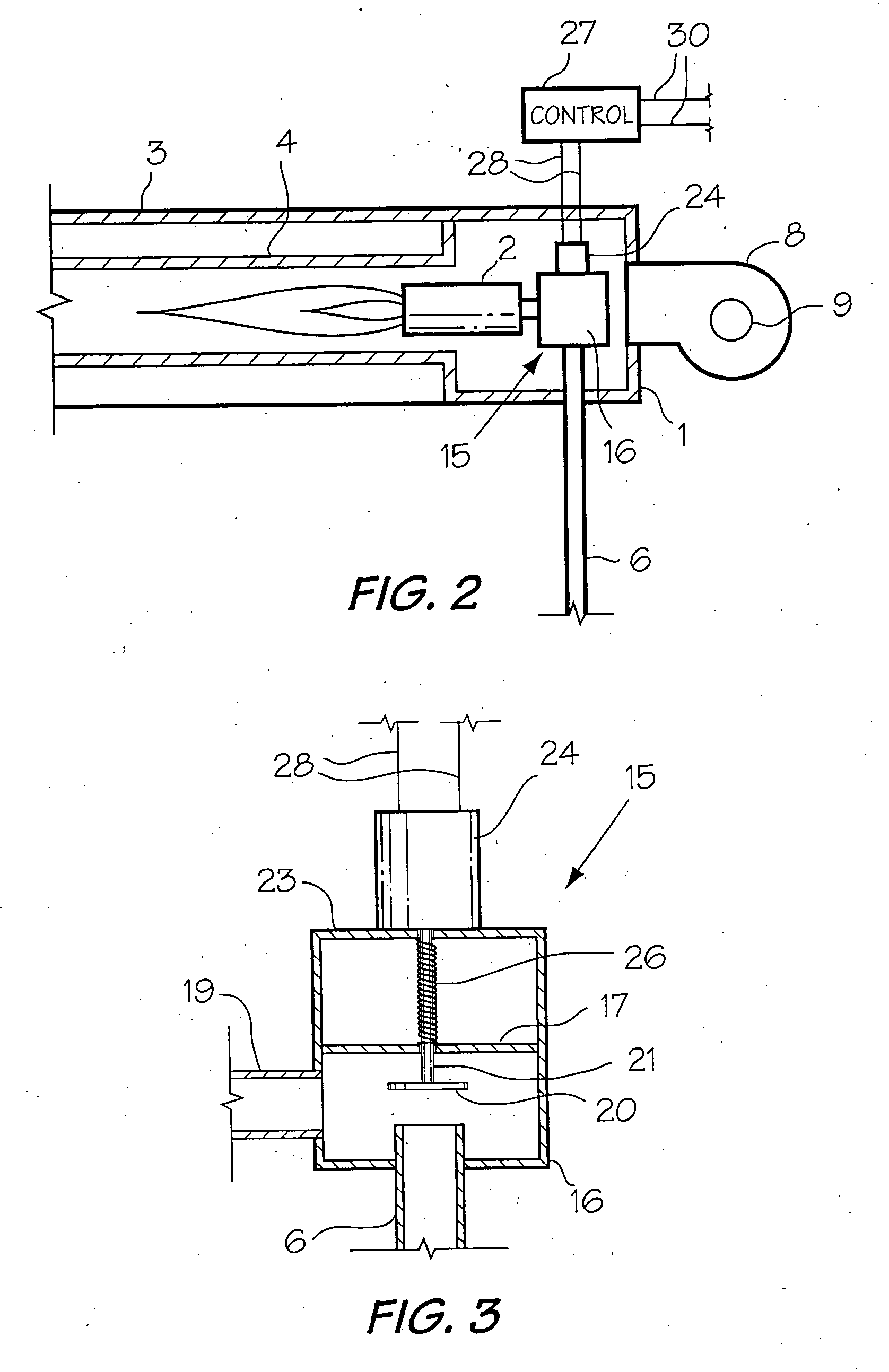
[0022] With reference to FIG. 2, a variable input, radiant tube heater in accordance with the invention includes most of the basic components of the heater of FIG. 1, namely a housing 1 carrying a burner 2, a reflector 3, a burner ...


PUM


Abstract

A variable input, radiant tube heater includes the usual housing containing a burner tube, a reflector connected to the housing, a fuel line into the housing and a pressure regulator in the fuel line. The blower is operated by a 24 volt motor and a transformer remote from the heater. Fuel flow is regulated by a regulator including a valve in the fuel line, a valve operator and an electrical control connected to the operator. For outdoor use heaters are supported by a modular frame including hollow beams, posts for supporting the beams and saddles for interconnecting the beams and mounting them on posts.

Description

CROSS REFERENCE TO RELATED APPLICATION [0001] This application claims priority on U.S. Provisional Application 60 / 618,164 filed Oct. 14, 2004.BACKGROUND OF THE INVENTION [0002] 1. Field of the Invention [0003] This invention relates to a radiant heater assembly and in particular to a radiant heating assembly for outdoor use. [0004] 2. Discussion of the Prior Art [0005] In general, there are several drawbacks to currently available radiant tube heaters. For example, most such heaters are single or dual input units. There are some systems which have a variable input utilizing a variable speed control vacuum pump in combination with a negative pressure gas valve (see CA 2,040,095, T. P. Seel). When the vacuum is increased or reduced, the change in pressure affects a negative pressure sensitive regulator in the gas valve to vary the amount of fuel to a burner. Another product on the market employs a gas valve using a source of compressed air to actuate a valve regulator and vary the fue...

Claims


Application Information

Patent Timeline
IPC IPC(8): F24C3/04
CPCF23C3/002F24C3/042F24D5/08
Inventor VANCAK, JOHN
Owner VANCAK JOHN
Learn More