Variable resistance device and a semiconductor apparatus, including a variable resistance layer made of a material with a perovskite structure

a technology of variable resistance and semiconductor apparatus, which is applied in the direction of semiconductor devices, electrical apparatus, basic electric elements, etc., can solve the problems of oxidizing contact plugs and transistor members, loss of regular crystal structure, and loss of variable resistance materials

Inactive Publication Date: 2006-04-20
PANASONIC CORP
View PDF4 Cites 35 Cited by
  • Summary
  • Abstract
  • Description
  • Claims
  • Application Information

AI Technical Summary

Problems solved by technology

However, a semiconductor apparatus using the above conventional memory device has two problems as follows.
The first problem is that the variable resistance layer 148, a high dielectric constant layer, or the like is deoxidized during the semiconductor manufacturing processes.
When the variable resistance layers of the variable resistance members are deoxidized, the regularity of the crystal structure is lost.
The second problem is that layers and the like made of variable resistance materials are likely subject to process damage during their formation and fabrication, and therefore, they are generally treated in a high-temperature oxygen atmosphere in order to eliminate such process damage.
However, it is sometimes the case that contact plugs and transistor members are oxidized during the treatment.
In such a case, polysilicon or tungsten used to form the contact plugs is susceptible to oxidation, which may lead to malfunction of a semiconductor apparatus after the completion of the manufacture.

Method used


Image

  • Variable resistance device and a semiconductor apparatus, including a variable resistance layer made of a material with a perovskite structure
  • Variable resistance device and a semiconductor apparatus, including a variable resistance layer made of a material with a perovskite structure
  • Variable resistance device and a semiconductor apparatus, including a variable resistance layer made of a material with a perovskite structure

Examples


embodiment 1

1. Embodiment 1

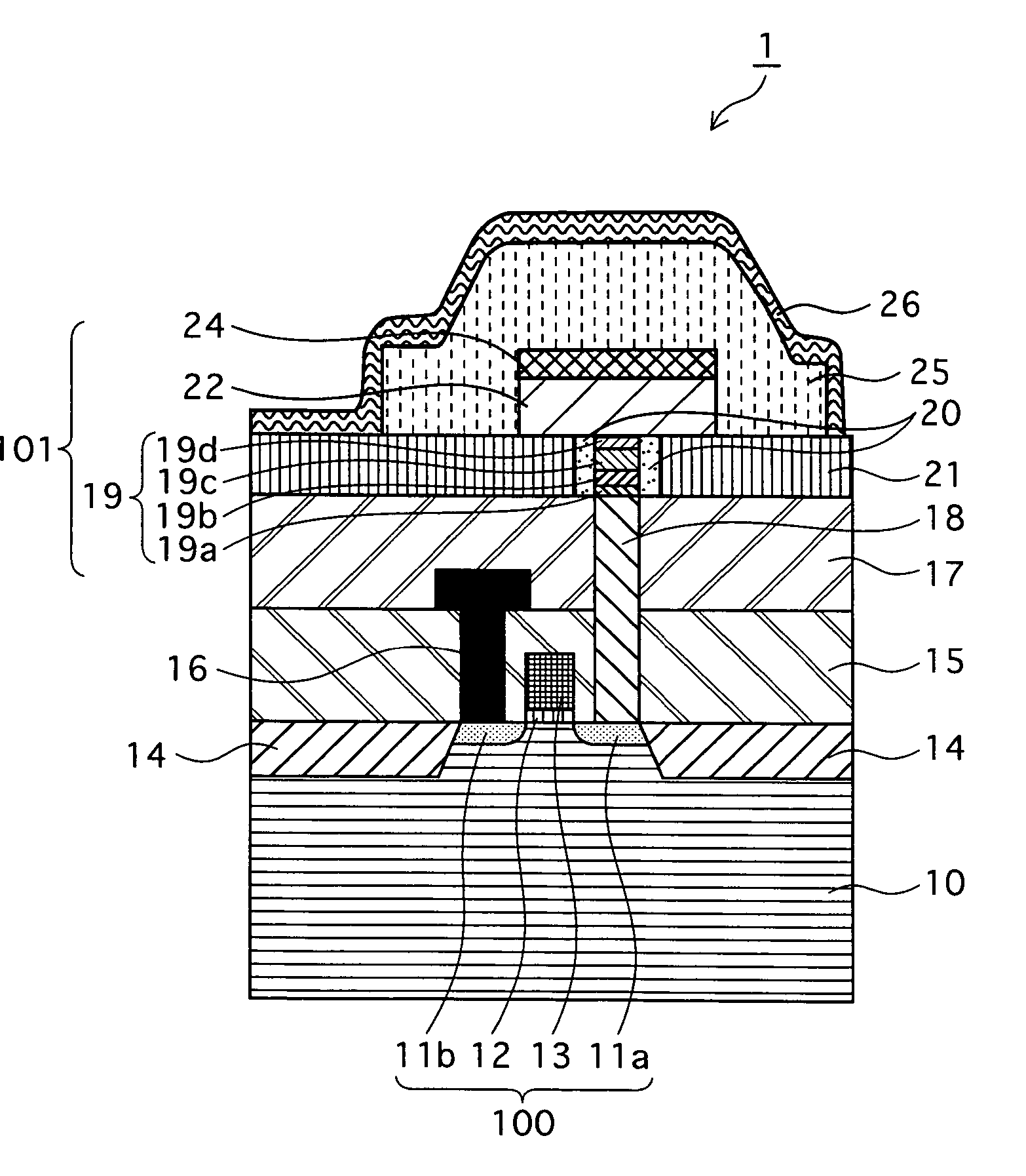
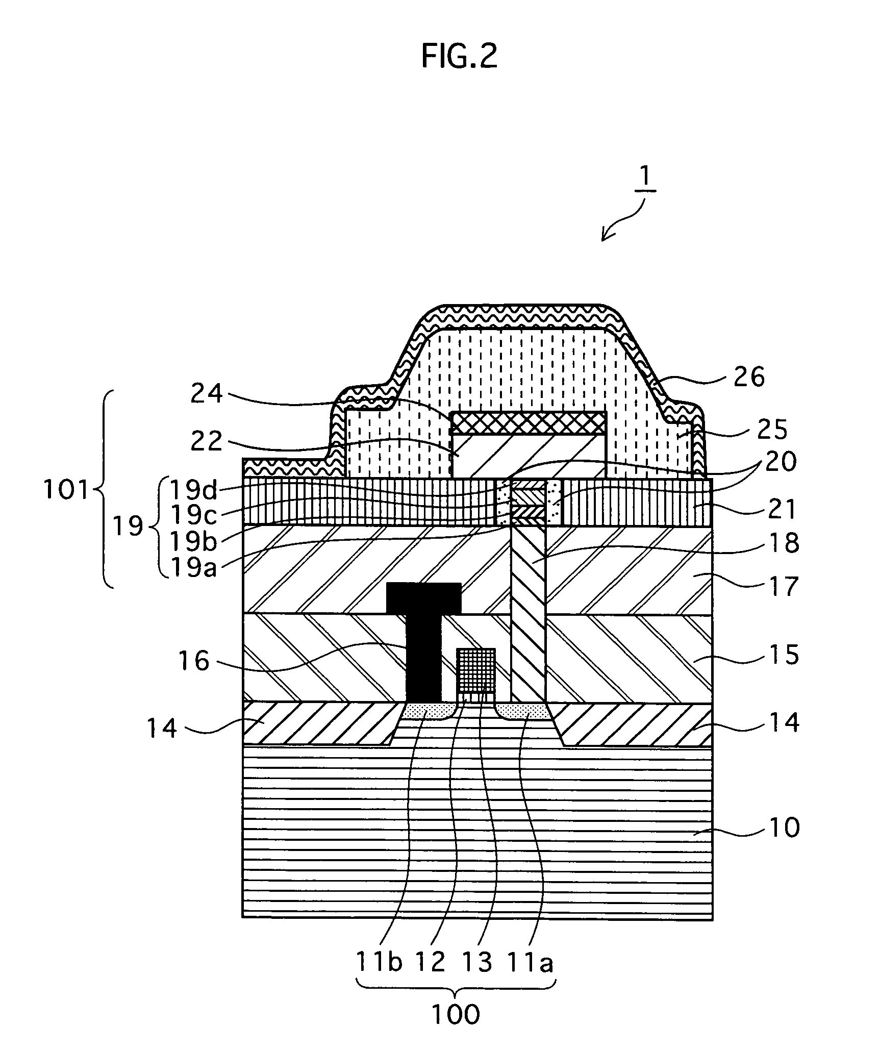
[0048] A memory device 1 of a semiconductor apparatus according to Embodiment 1 is described below, with the aid of FIGS. 2 to 6.

1.1 Structure of Memory Device 1

[0049] The structure of the memory device 1 is described in reference to FIG. 2. FIG. 2 is a schematic cross section showing the structure of the memory device 1 according to the present embodiment.

[0050] As shown in FIG. 2, the memory device 1 of the present embodiment has a structure in which, broadly speaking, a variable resistance member (a variable resistance switching unit) 101 and a selection field effect transistor member (referred to hereinafter as the “FET member”) 100 are integrated. Note that, although FIG. 2 depicts one variable resistance member 101 and one FET member 100, the memory device 1 may have a structure where multiple memory cells, each of which comprises a single variable resistance member 101 and a single FET member 100, are integrated.

[0051] As shown in FIG. 2, two sections where ...

embodiment 2

2. Embodiment 2

[0095] A memory device 2 of a semiconductor according to Embodiment 2 is described next with the reference to FIGS. 8A and 8B. Both figures are cross sections of the memory device 2 according to the present embodiment, with FIG. 8A showing a cross section of the memory device 2 along the line B-B (FIG. 8B) while FIG. 8B showing a cross section of the memory device 2 along the line A-A (FIG. 8A). FIGS. 8A and 8B illustrate: two memory cells being integrated, where each cell comprises a single variable resistance member 101 and a single FET member 100; and one memory-cell-plate transistor device 100c for supplying an electric potential to the upside electrodes of these two cells. However, the memory device 2 may have only one memory cell, or may have more than two memory cells.

[0096] As shown in FIG. 8A, the memory device 2 of the present embodiment further includes an insulating layer 27 made of silicon oxide and formed above the interlayer insulating layer 25, in add...

embodiment 3

3. Embodiment 3

[0101] A memory device 3 of a semiconductor apparatus according to Embodiment 3 is described next with reference to FIG. 9. FIG. 9 is a cross section of relevant parts showing a structure of the memory device 3 according to the present embodiment. Note that, although FIG. 9 depicts one variable resistance member 101a and one FET member 100, the memory device 3 may have a structure where multiple memory cells, each of which comprises a single variable resistance member 101a and a single FET member 100, are integrated.

[0102] As shown in FIG. 9, the memory device 3 according to the present embodiment has a structure in which a variable resistance member (variable resistance switching unit) 101a and the selection FET member 100 are integrated. The following describes a difference of the variable resistance member 101a from the variable resistance member 101 according to Embodiment 1 above.

[0103] In the variable resistance member 101 of Embodiment 1, the same paired elec...


PUM


Abstract

The present invention offers a variable resistance device and a semiconductor apparatus that have component parts less subject to damage and thereby ensure stable quality at a high yield, even if the manufacturing processes include operations in a deoxidizing atmosphere or an oxidizing atmosphere. The variable resistance device of the present invention comprises: a variable resistance layer made of a metal oxide and causing changes in electric resistance thereof in accordance with control conditions; and a hydrogen-diffusion preventing layer which surrounds at least part of the variable resistance layer and prevents hydrogen from diffusing into the variable resistance layer.

Description

BACKGROUND OF THE INVENTION [0001] 1. Field of the Invention [0002] The present invention relates to a variable resistance device and a semiconductor apparatus, in particular to the structure of the variable resistance device including a variable resistance layer made of a material with a perovskite structure. [0003] 2. Related Art [0004] Nonvolatile memories, in which stored data will not be lost even if a power supply is off, have undergone an explosive expansion in step with the development of mobile devices, such as digital still cameras and portable phones. Flash memories that accumulate charges on the floating gates of transistors have become the mainstream of conventional nonvolatile memories. However, it is difficult to scale tunnel oxide films forming the floating gates of flash memories while maintaining the nonvolatility, and therefore, next-generation nonvolatile memories have been awaited. [0005] In response to such demand, it has recently been proposed to construct a m...

Claims


Application Information

Patent Timeline
Patent Type & Authority Applications(United States)
IPC IPC(8): H01L29/00
CPCH01L27/112H01L45/12H01L45/1206H01L45/1253H01L45/1625H01L45/1675H01L27/2472H01L45/04H01L45/1233H01L45/147H01L27/2436H10B63/82H10B63/30H10N70/801H10N70/253H10N70/20H10N70/841H10N70/826H10N70/8836H10N70/026H10N70/063H10B20/00
Inventor TANAKA, KEISUKEKATO, YOSHIHISAWEI, ZHIQIANG
Owner PANASONIC CORP
Why Eureka
Try Eureka