EXAMPLE 2
[0052] Table 2 shows several suitable choices of diameter and areal density for microscopic holes suitable to relieve 1 cubic centimeter air bubble to atmosphere in less 5 seconds assuming a constant pressure differential of 1.2 kilo Pascals. Sheet thickness is 75 micrometers. Expectedly, the data shows that smaller holes must be applied with greater areal density to meet the specified venting time during installation of adhesive film to an article. Note that even for a 10 micrometer diameter hole the required areal density of 1,000 to 10,000 holes per square inch is realistic and technically attainable. TABLE 2 Time (seconds) required to relieve 1 cubic centimeter air Areal density of microscopic bubble for hole diameters holes [per square inch] 10 μm 32 μm 100 μm 1 2.6 10 3.6 0.26 100 0.36 1,000 3.2 10,000 0.32
[0053] As already noted, after the film is applied to the article surface and trapped air bubbles are avoided, gas evolution can still occur at the bond interface when the film is exposed to environment such as heat and light. Such gas is relieved by microscopic holes 27 and lifting and formation of bubbles are avoided. Since the rates at which such gas is evolved are very low, microscopic holes 27 can be very small (typically 1 to 10 micrometers) and installed with low areal density (1 to 1000 per square inch).
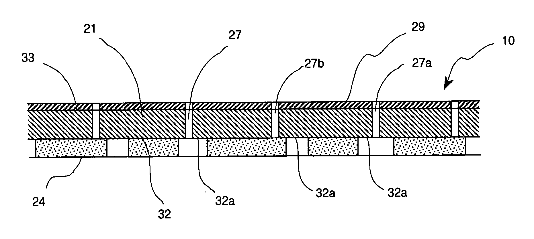
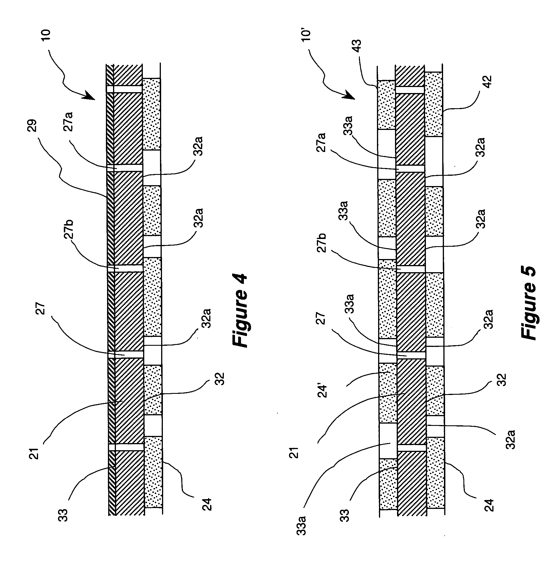
[0054] Referring further to FIG. 4, the adhesive film 10 may also include a layer 29 attached to surface 33 of substrate 21. Layer 29 can be a print ink, protective coating, or decorative coating. Alternately, layer 29 may be a composite layer comprising separate sublayers which may include print ink, protective coating, or decorative coating. Whichever the case, microscopic holes 27 penetrate through the layer of material 29 to provide air permeability for the film 10.
[0055] Microscopic holes 27 may be installed either before or after the adhesive 24 is applied to the substrate 21. Preferably, the holes are installed after providing the substrate 21 with the finish layer 29. When the holes are installed after coating the substrate with adhesive 24, some of the holes 27 may actually penetrate through the adhesive. Depending on the process for production of the holes 27 and the nature of the adhesive 24, holes 27 penetrating through adhesive 24 may become at least partially closed with passage of time. Holes that remain at least partially open increase the air permeability of the film 10. Adhesive film 10 may also include a release liner attached to surface 43 the adhesive 24. Furthermore, the substrate 21 of adhesive film 10 may be also embossed for decorative or other beneficial purposes.
[0056] Suitable techniques for installation of the holes 27 include mechanical piercing, electric discharge, and laser drilling. Mechanical piercing method and apparatus suitable for production of holes in the manufacture of the subject adhesive sheet is disclosed by Silverstein in the U.S. Pat. No. 3,789,710. Silverstein's method and apparatus use a heat assisted piercing and are particularly effective for use on substrates made of thermoplastic material. Mechanical piercing can produce holes down to about 0.020 inch diameter.
[0057] The use of electric discharge for perforation of dielectric sheet materials has been practiced commercially since the 1940's. Devices and methods for electric discharge perforation have been disclosed by Meaker in the U.S. Pat. No. 2,340,546; Menke in the U.S. Pat. No. 2,528,157; Bancroft et al. in the U.S. Pat. No. 3,385,951; Martin in the U.S. Pat. No. 4,029,938; and Whitman in the U.S. Pat. No. 4,447,709. Electric discharge can produce holes down to about 0.030 inch diameter.
[0058] Laser drilling has become a well established commercial practice since its initial introduction in the 1970's. General review of the state of the art in laser drilling is presented by Leo Rakowski in “Non-Traditional Methods for Making Small Holes,” published in Modern Machine Shop, June 2002 issue, pages 76-83. Devices and methods for laser drilling have been disclosed by Lilly et al. in the U.S. Pat. No. 4,410,785; Kimbara et al., in the U.S. Pat. No. 4,568,815; Fukuchi in the U.S. Pat. No. 5,403,990; Steadman in the U.S. Pat. No. 6,344,256; and Hamada in the U.S. Pat. No. 6,720,524. Equipment for laser drilling of the holes suitable for use with the subject invention may also include means for detecting adhesive free portions of surface 33 and preferentially installing the hole (s) at such locations. Laser drilling is particularly suitable for production of precision-located holes smaller than 30 micrometers and as small as about 1 micrometer in diameter.
[0059] Referring now to FIG. 5, there is shown a side cross-sectional view of an adhesive film 10′ in accordance with a variant of first embodiment of the subject invention. In this variant, the substrate 21 is coated with pressure sensitive adhesive on both faces: surface 32 is coated with adhesive 24 and surface 33 is coated with adhesive 24′. In each case, the adhesive coating is applied discontinuously so that portion 32a of surface 32 and portion 33a of surface 33 remain generally free of the adhesive. Preferably, the adhesive covers less than 90% of each the surface 32 and 33. The adhesive may be applied in regular, irregular, or entirely random patterns. Examples of suitable patterns are straight lines, stripes, wavy lines, curves, dots, shapes, checkered, crosshatched, and any combination thereof. If regular patterns are employed, preferably they should be coordinated and well aligned so that a high percentage of uncoated portions 32a and 33a lay directly opposite to each other. A pattern for microscopic holes 27 is preferably chosen so that a large percentage of the holes are at locations where they connect opposing uncoated portions 32a and 33a. Adhesives 24 and 24′ can be both of the same type or different types. An example of two different types of adhesives that may be simultaneously used with adhesive film 10′ are permanent pressure sensitive adhesive and a temporary pressure sensitive adhesive. Adhesive film 10′ may also include a release liner attached to surface 42 the adhesive 24 and/or surface 43 of adhesive 24′.
[0060] Referring now to FIG. 6, there is shown a side cross-sectional view of an adhesive film 11 in accordance with a second embodiment of subject invention. This embodiment is similar to the first embodiment except that 1) pressure sensitive adhesive 124 is applied substantially continuously over the surface 32 of substrate 21, and 2) the pressure sensitive adhesive 124 is porous and permeable by air. Suitable porous pressure sensitive adhesive has been disclosed in prior art for example by Copeland in the U.S. Pat. No. 3,121,021. Holes 27 can be installed in any suitable pattern either before or after the adhesive 124 is applied to substrate 21. Since the adhesive 124 is porous, a large percentage of the holes 27 will connect to one or more pores in adhesive 124 leading up to surface 43. Air trapped between the adhesive film 11 and adherent article is then relieved by first passing through the adhesive 124 and then through holes 27 into the atmosphere.
[0061] Referring now to FIG. 7, there is shown a side cross-sectional view of an adhesive film 12 in accordance with a third embodiment of subject invention. This embodiment is similar to the first embodiment except that 1) the adhesive 224 is applied substantially continuously over the surface 32 of substrate 21, 2) the adhesive 224 can be either pressure sensitive or solvent activated, and 3) holes 27 penetrate through the adhesive 224.
[0062] Those skilled in the art can now appreciate from the foregoing description that the broad teachings of the subject invention can be implemented in a variety of forms. Therefore, while this invention has been described in connection with particular examples thereof, the true scope of the invention should not be limited since other modifications will become apparent to the skilled practitioner upon a study of the drawings and the following claims.