Engine exhaust gas cleaning method and system

a technology for cleaning methods and exhaust gas, applied in the direction of machines/engines, exhaust treatment electric control, electrical control, etc., can solve the problems of environmental pollution, cleaning rate, cleaning rate, etc., and achieve the effect of reducing the emission amount of particular components, high cleaning rate, and effective reduction of cleaning ra

Inactive Publication Date: 2006-04-27
HITACHI LTD
View PDF10 Cites 112 Cited by
  • Summary
  • Abstract
  • Description
  • Claims
  • Application Information

AI Technical Summary

Benefits of technology

[0025] With the engine exhaust gas cleaning method and system of the present invention, it is possible to effectively reduce emission amounts of particular components, such as NOx, contained in exhaust gas by adding an additive, such as urea water or light oil, into an exhaust passage. Further, the method and system of the present invention are adaptable for a reduction of the cleaning rate caused by deterioration of a catalyst, can always maintain a high cleaning rate during acceleration and deceleration as well, and can minimize environmental pollution with use of the additive in the least necessary amount.

Problems solved by technology

However, it has hitherto been usual that no considerations are paid to a reduction of the cleaning rate caused by deterioration of the catalyst, and the reduction of the cleaning rate is compensated for by injecting, as an additive, urea water or ammonia water in large amount.
In spite of urea water or ammonia water being substances present in the natural world, if a large amount of urea water or ammonia water is used in an engine exhaust system, there is a risk causing environmental pollution, such as an irritating odor of ammonia.

Method used


Image

  • Engine exhaust gas cleaning method and system
  • Engine exhaust gas cleaning method and system
  • Engine exhaust gas cleaning method and system

Examples


Embodiment Construction

[0042] An embodiment of the present invention will be described below with reference to the drawings.

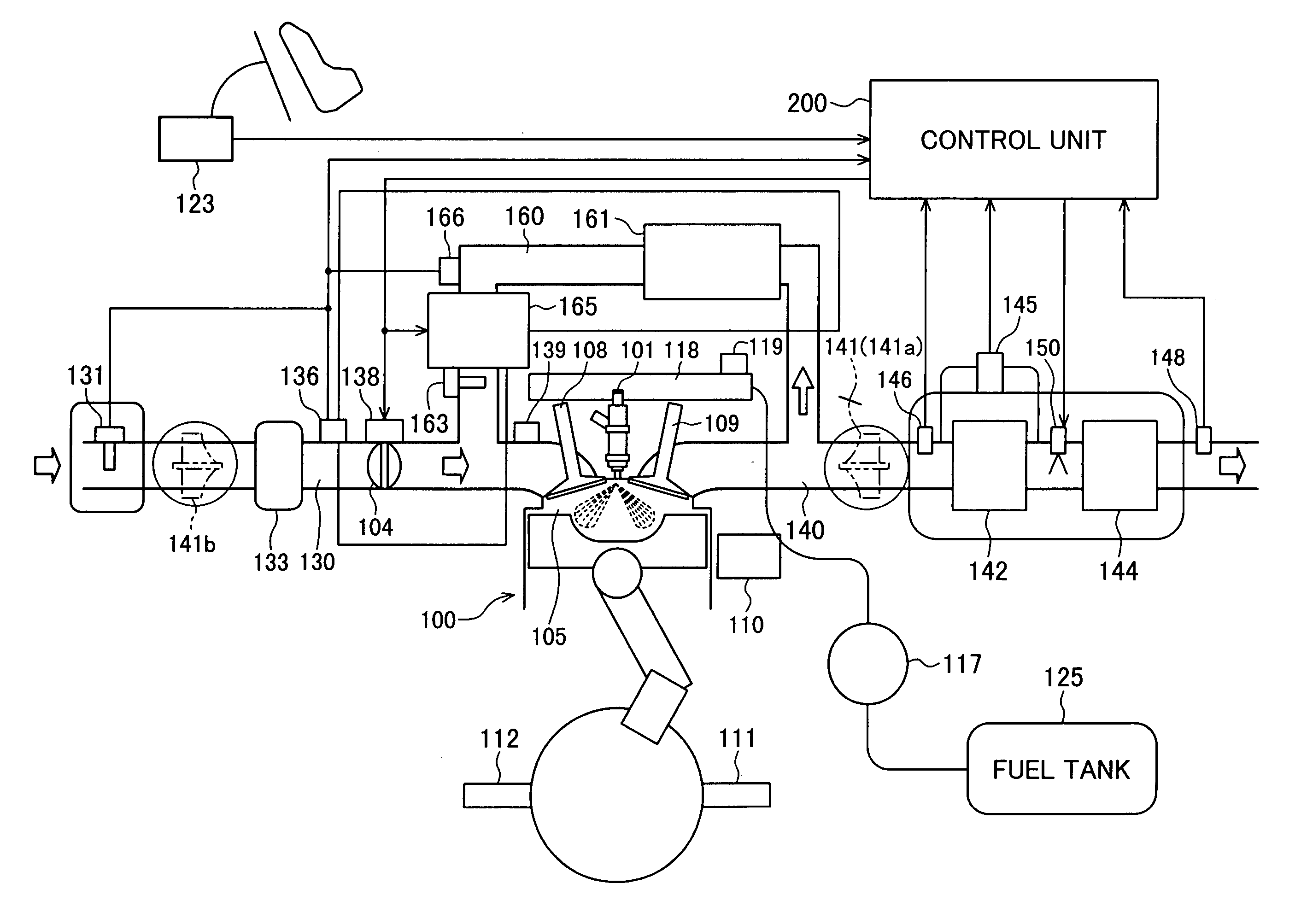
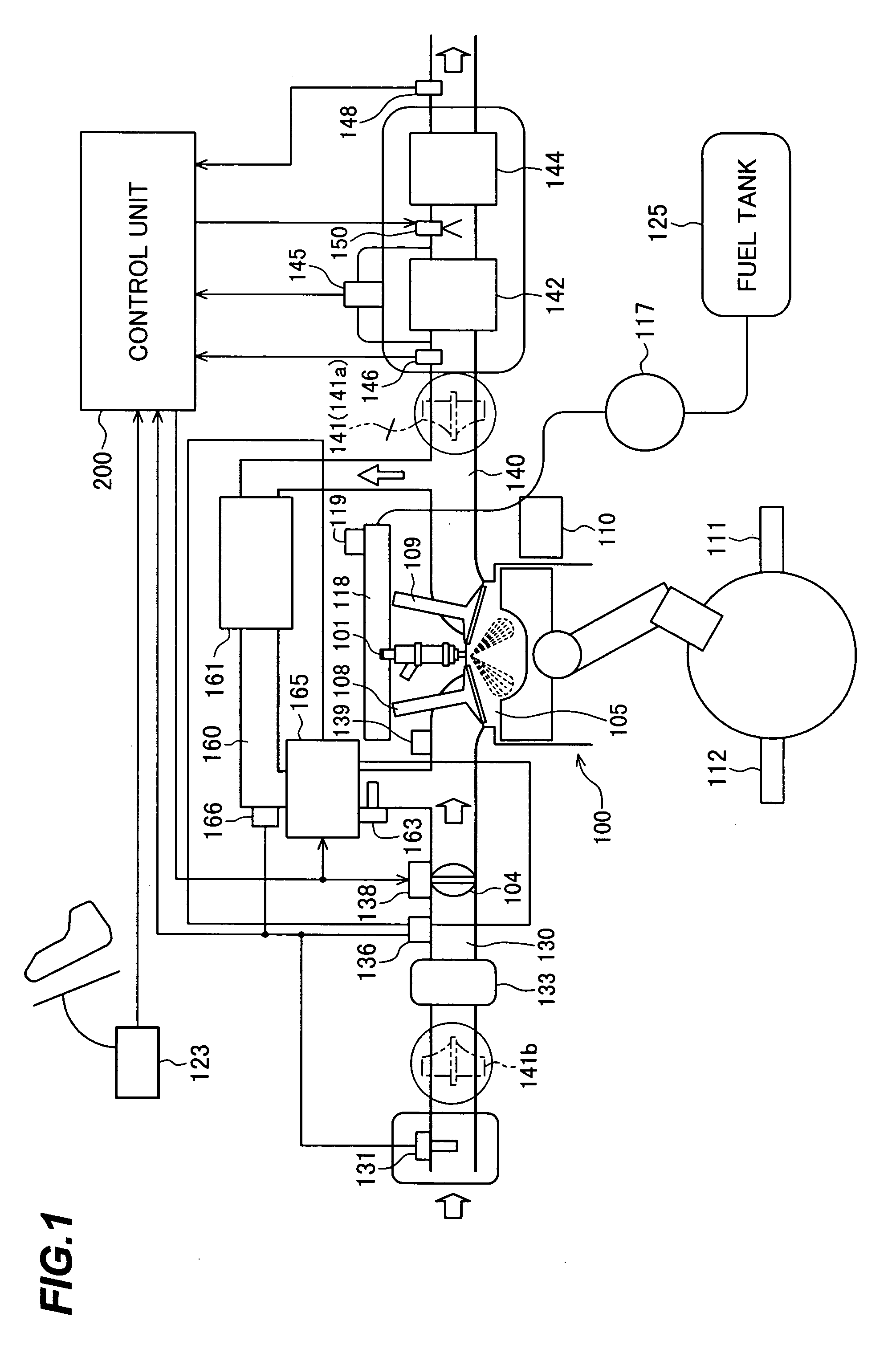
[0043]FIG. 1 is a schematic view of an engine to which an engine exhaust gas cleaning method according to the present invention is applied, including a control system for the engine.

[0044] An engine 100 is a vehicle-loaded diesel engine, for example, and includes an intake valve 108, an exhaust valve 109, a fuel injection valve (fuel injection nozzle) 101, an electronically controlled throttle valve 104, a water temperature sensor 110, a crank angle sensor 111, a cam angle sensor 112, etc. Fuel is transported from a fuel tank 125 by a high-pressure fuel pump 117, then stored in a common rail 118, and is injected into a combustion chamber 105 from the fuel injection valve 101. The fuel pressure in the common rail 118 is detected by a fuel pressure sensor 119 and is inputted to a control unit 200. A pressure boosted by the high-pressure fuel pump 117 is regulated by a fuel pressure c...


PUM


Abstract

An engine exhaust gas cleaning method and system, which can effectively reduce emission amounts of particular components, such as NOx, contained in exhaust gas by adding an additive, such as urea water or light oil, into an exhaust passage, which is adaptable for a reduction of the cleaning rate caused by deterioration of a catalyst, which can always maintain a high cleaning rate during acceleration and deceleration as well, and which can minimize environmental pollution with use of the additive in the least necessary amount. The engine exhaust gas cleaning system comprises a catalyst for removing a particular component, represented by NOx, contained in exhaust gas of an engine, an additive adding unit for adding, to the exhaust gas, an additive for reducing the particular component represented by NOx, and an EGR amount adjusting unit for adjusting an EGR amount. An addition amount of the additive and the EGR amount are set depending on an operating state and deterioration of the catalyst with time. The catalyst is regenerated when a cleaning capability of the catalyst has reduced to a predetermined value or below.

Description

BACKGROUND OF THE INVENTION [0001] 1. Field of the Invention [0002] The present invention relates to a method and a system for cleaning exhaust gas of an engine. More particularly, the present invention relates to an engine exhaust gas cleaning method and system which are adapted for an engine provided with a catalyst for removing particular components, such as NOx, contained in exhaust gas and an additive adding unit for adding, to the exhaust gas, an additive for reducing the particular components. [0003] 2. Description of the Related Art [0004] Recently, even severer standards have been applied in emission control. Exhaust gas of a diesel engine contains HC, CO, NOx, PM, etc. PM is removed by using a filter (DPF=Diesel Particulate Filter) that is able to trap the PM. HC and CO can be removed by a catalyst having an oxidation action. On the other hand, an emission amount of NOx cannot be reduced to 0 even with modification of engine control parameters, such as an amount of EGR (Ex...

Claims


Application Information

Patent Timeline
Patent Type & Authority Applications(United States)
IPC IPC(8): F02M25/06F01N3/00
CPCF01N3/035F01N3/0814F01N3/0821F01N3/0842F01N3/0885F01N3/208F01N9/007F01N11/00F01N2550/03F01N2560/026F01N2610/02F01N2610/03F01N2610/04F02B37/00F02D41/005F02D41/0275F02D41/107F02M25/0707F02M25/0718F02M25/0746F02M25/0754Y02T10/47Y02T10/24F01N13/009F02M26/05F02M26/15F02M26/40F02M26/47Y02T10/12Y02T10/40
Inventor KATOGI, KOZOICHIHARA, TAKANOBU
Owner HITACHI LTD
Why Eureka
Try Eureka