Substrate conveyor apparatus, substrate conveyance method and exposure apparatus

a conveyor and substrate technology, applied in the direction of photomechanical equipment, instruments, printing, etc., can solve the problems of high yield, easy and reliably prevented contamination of the inner surface of the protective cover, and high yield

Active Publication Date: 2006-04-27
NIKON CORP
View PDF15 Cites 350 Cited by
  • Summary
  • Abstract
  • Description
  • Claims
  • Application Information

AI Technical Summary

Benefits of technology

[0021] In the substrate conveyor apparatus of the present invention, when the substrate is used, the inner surface of the protective cover is concealed by a cover protection means, therefore when the substrate is used, contamination of the inner surface of the protective cover can be easily and reliably prevented.
[0022] In addition, in the substrate conveyor apparatus of the present invention, the substrate or the protective cover are grounded by a grounding means, therefore electrostatic charging of the substrate or the protective cover can be easily and reliably prevented.
[0023] In the substrate conveyance method of the present invention, when the substrate is used, the protective cover is held in standby in a state wherein the inner surface of the protective cover is concealed, therefore contamination of the inner surface of the protective cover can be easily and reliably prevented.
[0024] In the exposure apparatus of the present invention, substrates with little contamination are used, obtaining a product with high yield.

Problems solved by technology

However, in the above method, there was the problem that the protective cover for the reticle used during exposure is left in a state wherein the inner surface of the protective cover is exposed, and it is easy for particles and the like to become adhered to the inner surface of the protective cover.

Method used


Image

  • Substrate conveyor apparatus, substrate conveyance method and exposure apparatus
  • Substrate conveyor apparatus, substrate conveyance method and exposure apparatus
  • Substrate conveyor apparatus, substrate conveyance method and exposure apparatus

Examples


first embodiment

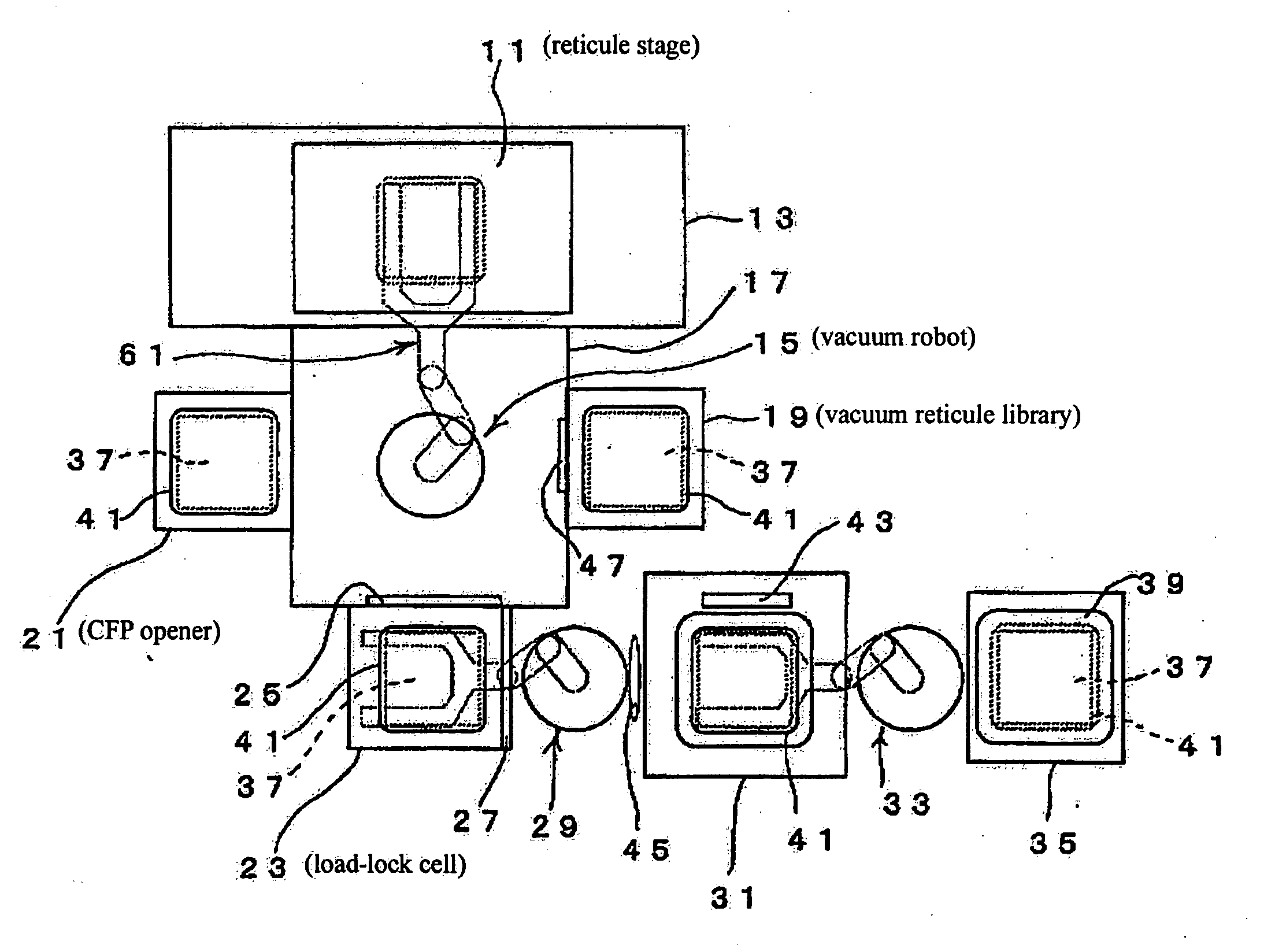
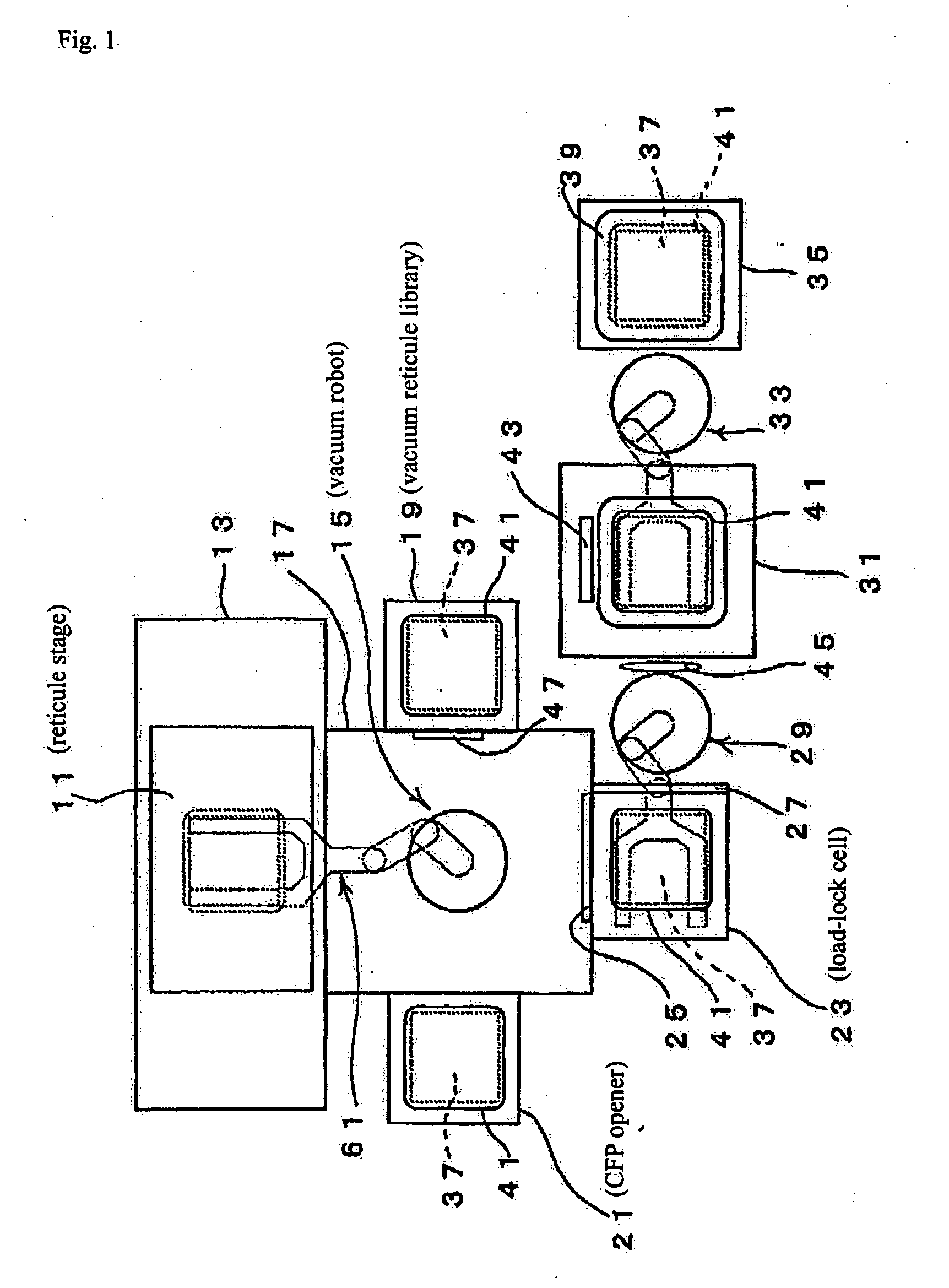
[0035]FIG. 1 shows the first embodiment of the substrate conveyor apparatus of the present invention.

[0036] This substrate conveyor apparatus is provided adjacent to an exposure chamber 13 wherein reticle stage 11 and the like are disposed. On one side of reticle chamber 13, a robot chamber 17 is provided wherein a vacuum robot 15 is disposed. On one side of robot chamber 17, a vacuum reticle library 19 is provided, and on the other side a clean filter pod opener 21 (hereafter called “CFP opener”) is provided. Exposure chamber 13, robot chamber 17, vacuum reticle library 19 and CFP opener 21 are in vacuum atmosphere.

[0037] In the position where robot chamber 17 faces exposure chamber 13, a load-lock cell 23 is disposed. Load-lock cell 23 communicates to robot chamber 17 via a second gate valve 25. In addition, [load-lock cell 23] communicates to atmospheric air via a first gate valve 27.

[0038] On the other side of load-lock cell 23, a reticle carrier opener 31 is disposed via a s...

embodiment 2

[0050]FIG. 7 shows a second embodiment of the substrate conveyor apparatus of the present invention.

[0051] Note that in this embodiment, the same members as in the first embodiment are assigned the same symbols, so detailed explanation has been omitted.

[0052] In this embodiment, as shown in FIG. 7(a), the cover member 65 that is a protective cover is mounted so that it can be attached and removed and so that it conceals only pattern 37b on reticle 37.

[0053] Then, as shown in FIG. 7(b), cover member 65 is conveyed as mounted to cover member 65 by conveyor arm 61 to static chuck 63 of reticle stage 11, then only reticle 37 is chucked to static chuck 63.

[0054] On the other hand, as shown in FIG. 7(c) cover member 65, which remains on conveyor arm 61, is conveyed to a standby part by conveyor arm 61. In the standby part, as shown in FIG. 7(d), an imitation part 67 that imitates the shape of reticle 37 is disposed, and by mounting cover member 65 to this imitation member 67, the inne...

embodiment 3

[0057]FIG. 8 shows a third embodiment of the substrate conveyor apparatus of the present invention.

[0058] Note that in this embodiment, the same members as in the first embodiment are assigned the same symbols, so detailed explanation has been omitted.

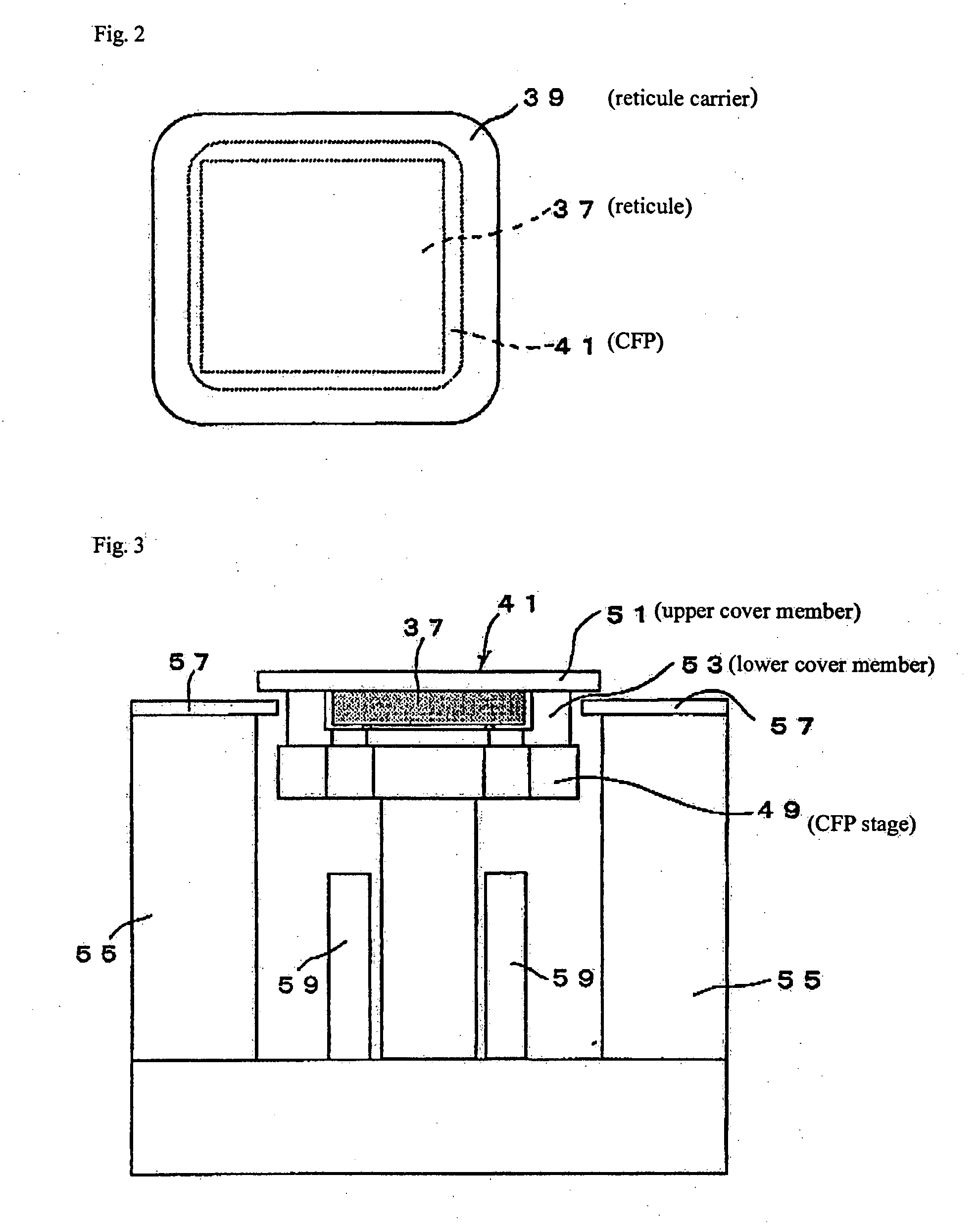
[0059] In this embodiment, a stage-side conductive layer 69 made of aluminum is formed on the upper surface of CFP stage 49 (setting machine) of CFP opener 21, for example. This stage-side conductive layer 69 is grounded via ground wire 71.

[0060] On the other hand, on the side surface of lower cover member 53 of CFP 41, when lower cover member 53 is set on stage-side conductive layer 69, a lower cover conductive layer 53b that contacts stage-side conductive layer 69 is formed. This lower cover conductive layer 53b contacts an upper cover conductive layer 51b formed on upper cover member 51 when upper cover member 51 is set on lower cover member 53. Also, on the upper surface of reticle 37, when upper cover member 51 is set, a reticl...


PUM

PropertyMeasurementUnit
wavelengthaaaaaaaaaa
shapeaaaaaaaaaa

Abstract

With respect to a substrate conveyor apparatus that, being a substrate conveyor apparatus that carries substrates on which patterns are formed, carries the substrates in a state protected by a protective cover when the substrate is not used, a substrate conveyor apparatus having a cover protection means that conceals the inner surface of the protective cover when the substrate is used.

Description

BACKGROUND OF THE INVENTION [0001] The present invention pertains to a substrate conveyor apparatus that carries substrates on which patterns are formed to a substrate exposure apparatus equipped with a substrate conveyance method and a substrate conveyor apparatus. [0002] With reticles (also known as masks) used in next-generation lithography such as EPL and EUVL, a common problem is the weakness that pericles that prevent the adhering of defect-causing particles onto the reticle pattern face cannot be used. [0003] As a means to resolve this problem, there is a proposal to attach a protective cover when a reticle is not used and only remove it during exposure. For example, refer to U.S. Pat. No. 6,239,863. SUMMARY OF THE INVENTION [0004] However, in the above method, there was the problem that the protective cover for the reticle used during exposure is left in a state wherein the inner surface of the protective cover is exposed, and it is easy for particles and the like to become ...

Claims


Application Information

Patent Timeline
Patent Type & Authority Applications(United States)
IPC IPC(8): G03B27/58G03F1/66G03F7/20H01L21/027H01L21/673H01L21/677
CPCB82Y10/00B82Y40/00G03F1/24G03F1/48H01L21/67742G03F7/70741G03F7/70983H01L21/67196H01L21/67225G03F1/62G03F1/66G03F7/70733G03F7/7075G03F7/70908G03F7/70916B25J11/0095H01L21/68707
Inventor HIRAYANAGI, NORIYUKI
Owner NIKON CORP
Why Eureka
Try Eureka