In-situ droplet monitoring for self-tuning spectrometers

a droplet monitoring and spectrometer technology, applied in the direction of dispersed particle separation, instruments, separation processes, etc., to achieve the effect of improving the accuracy and precision of analytical measurement, stable analytical signal, and fast droplets

Active Publication Date: 2006-04-27
GEORGE WASHINGTON UNIV THE
View PDF16 Cites 22 Cited by
  • Summary
  • Abstract
  • Description
  • Claims
  • Application Information

AI Technical Summary

Benefits of technology

[0019] In pneumatic nebulization, higher gas flow rates are required to produce fine droplets, however, such high flows yield fast droplets that may survive the plasma. This trade-off is particularly important for direct injection devices where no filtering is performed on the aerosol before their introduction into the ICP. For the best analytical performance, small droplets must be focused into the axial channel of the ICP at low velocities (<15 m/s), and via a narrow cone, much narrower than the aerosol cone provided by the current direct injection nebulizers. A longer torch may also be used to accommodate a longer residence time for directly introduced droplets. However, the prediction of an optimum length requires a detailed knowledge on both size and velocity of the droplets throughout the plasma. The exemplary techniques described herein in the conte...

Problems solved by technology

In pneumatic nebulization, higher gas flow rates are required to produce fine...

Method used


Image

  • In-situ droplet monitoring for self-tuning spectrometers
  • In-situ droplet monitoring for self-tuning spectrometers
  • In-situ droplet monitoring for self-tuning spectrometers

Examples


Embodiment Construction

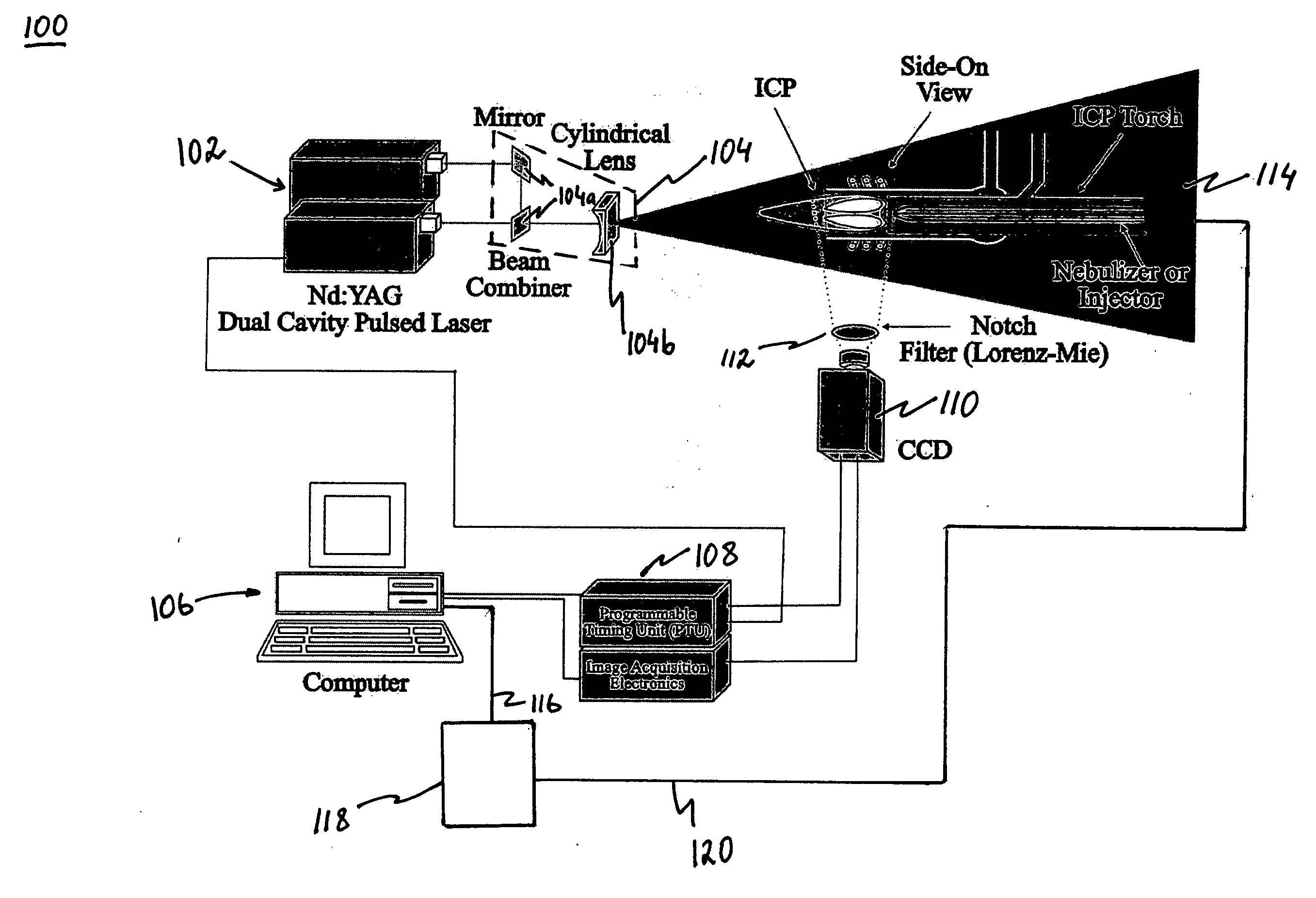
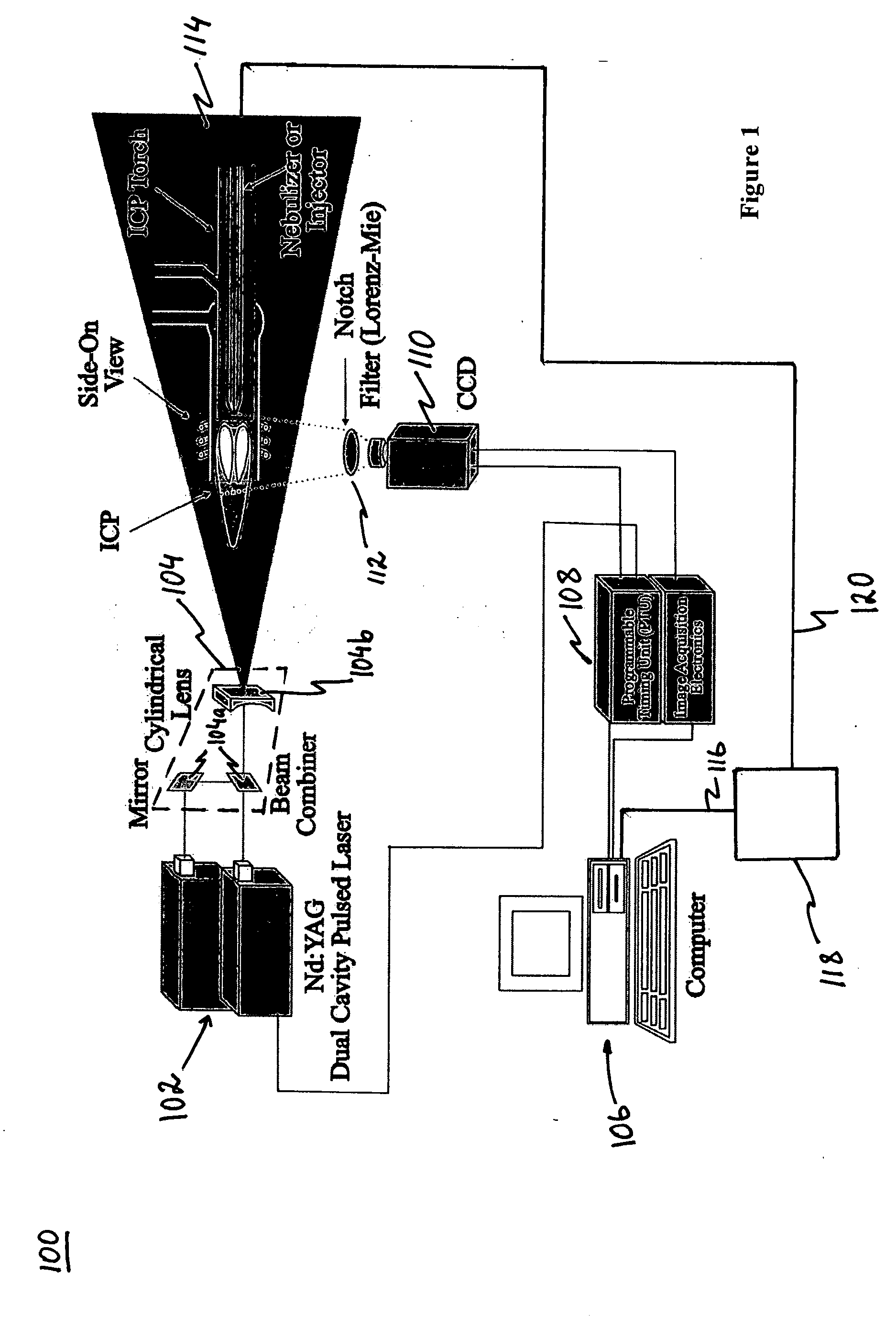
[0029] The concepts and devices presented here can be used to monitor droplets and their characteristics as they undergo desolvation and evaporation in a plasma or a flame source. This information (e.g. droplet number density, droplet size and velocity) can then be used as a feedback signal to optimize the droplet generation and / or source and spectrometer operating parameters to obtain a stable analytical signal. Although in an embodiment of the present invention, the in-situ measurements described below are centered on an inductively coupled plasma source, it should be appreciated by those skilled in the art that the in-situ measurements are equally applicable to other sources.

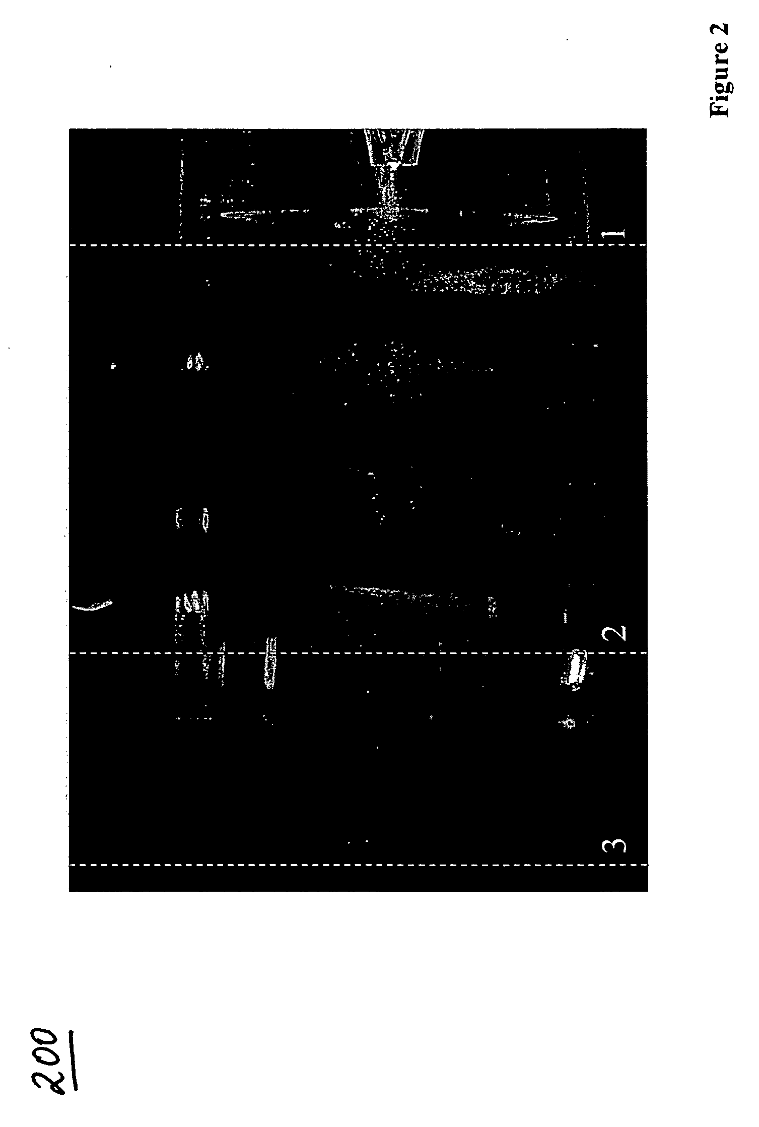
[0030] To illustrate the potentials of the proposed technique in creating data suitable for tunable spectrometer, the droplet size and velocity information is presented for three diverse nebulization systems. The nebulization systems include: 1) a direct injection high efficiency nebulizer (Model DIHEN-170-A...


PUM


Abstract

A laser scattering based imaging technique is utilized in order to visualize the aerosol droplets in an inductively coupled plasma (ICP) torch from an aerosol source to the site of analytical measurements. The resulting snapshots provide key information about the spatial distribution of the aerosol introduced by direct and indirect injection devices: 1) a direct injection high efficiency nebulizer (DIHEN); 2) a large-bore DIHEN (LB-DIHEN); and 3) a PFA microflow nebulizer with a PFA Scott-type spray chamber. Moreover, particle image velocimetry (PUV) is used to study the in-situ behavior of the aerosol before interaction with, for example, plasma, while the individual surviving droplets are explored by particle tracking velocimetry (PTV). Further, the velocity distribution of the surviving droplets demonstrates the importance of the initial droplet velocities in complete desolvation of the aerosol for optimum analytical performance in ICP spectrometries. These new observations are important in the design of the next-generation direct injection devices for lower sample consumption, higher sensitivity, lower noise levels, suppressed matrix effects, and for developing smart spectrometers. For example, a controller can be provided to control the output of the aerosol source by controlling the configuration of the source or the gas flow rate via feedback information concerning the aerosol.

Description

CROSS REFERENCE TO A RELATED PATENT AND CLAIM TO PRIORITY [0001] Related subject matter is disclosed in U.S. Pat. No. 6,166,379, entitled “Direct Injection High Efficiency Nebulizer For Analytical Spectrometry”, issued on Dec. 26, 2000 to Akbar Montaser et al. This application claims benefit under 35 U.S.C. §119(e) of provisional patent application Ser. No. 60 / 615,542 filed on Oct. 1, 2004. The entire disclosures of said patent and provisional application are hereby incorporated by reference.[0002] This application was made with United States Government Support under Grant No. DE-FG02-93ER14320 awarded by the U.S. Department of Energy and under Grant Nos. CHE-9505726 and CHE-9512441 awarded by the National Science Foundation. The U.S. Government has certain rights in the invention.BACKGROUND OF THE INVENTION [0003] 1. Field of the Invention [0004] This application relates generally to nebulizers for use in analytical spectrometry such as inductively coupled mass spectrometry, as wel...

Claims


Application Information

Patent Timeline
IPC IPC(8): G01N21/00
CPCG01N15/065G01N15/1463G01N2015/1075G01N2015/1486G01N2015/1493
Inventor MONTASER, AKBARJORABCHI, KAVEHKAHEN, KAVEH
Owner GEORGE WASHINGTON UNIV THE
Why Eureka
Try Eureka