3-Bit NROM flash and method of operating same

a technology of nrom flash and nrom cell, which is applied in the direction of read-only memories, static storage, instruments, etc., can solve the problems of complex programming circuitry, read circuitry, and the need to detect four threshold voltage ranges, so as to increase the storage capacity of an nrom array, improve the operation of the nrom cell, and increase the density

Active Publication Date: 2006-05-04
TOWER SEMICONDUCTOR
View PDF10 Cites 2 Cited by
  • Summary
  • Abstract
  • Description
  • Claims
  • Application Information

AI Technical Summary

Benefits of technology

[0017] Accordingly, the present invention provides an NROM array that exhibits an increased density, without exceeding the physical limitations of a conventional NROM cell. In one embodiment, the present invention increases the storage capacity of an NROM array by 50%. As described above (FIG. 2), a conventional NROM cell stores two data bits, one in each of two physically separate nodes of the NROM cell. The present invention modifies the operation of the NROM cell, such that the NROM cell stores three threshold voltage (VT) states in each storage node of the NROM cell. That is, each storage node of the NROM cell can be in an erased state, a moderately programmed state, or a fully programmed state.
[0018] In accordance with one embodiment, NROM cells are logically grouped in pairs. A data value is read from a pair of NROM cells in the following manner. A first charge trapping regions in a first NROM cell and a first charge trapping region in a second NROM cell are subject to a read operation, wherein the threshold voltage states associated with these charge trapping regions are determined. Because each charge trapping region has three possible states, reading the first and second NROM cells can provide nine possible combinations (3*3=9). Eight of these nine combinations are decoded into three binary bits. In this manner, a pair of charge trapping regions in the first and second NROM cells provide 3-bits of data. Because each NROM cell includes two separate charge trapping regions, two NROM cells can store a total of 6-bits of data (2*3=6). Consequently, the average storage density is therefore increased from two bits per NROM cell to three bits per NROM cell.
[0019] The present invention will be more fully understood in view of the following description and drawings.

Problems solved by technology

The Strata-Flash NVM cell requires precise programming of the threshold voltage, such that complex programming circuitry must be provided.
In addition, the read circuitry, which must detect four threshold voltage ranges, is also relatively complex.
Moreover, even slight drifting of the programmed threshold voltage (e.g., ½ Volt or less) can result in errors.

Method used


Image

  • 3-Bit NROM flash and method of operating same
  • 3-Bit NROM flash and method of operating same
  • 3-Bit NROM flash and method of operating same

Examples


Embodiment Construction

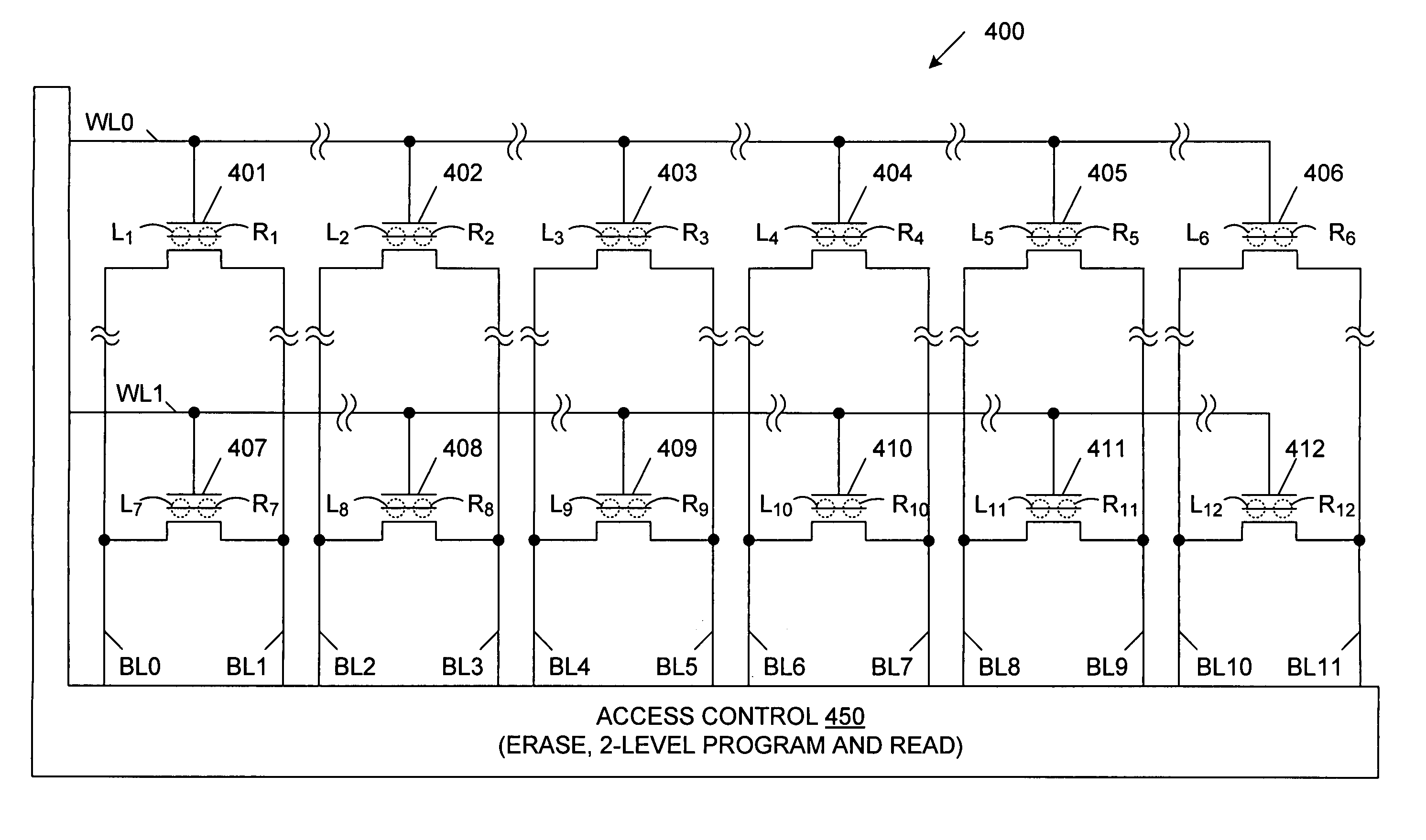
[0026]FIG. 4 is a circuit diagram of an NROM array 400 in accordance with one embodiment of the present invention. NROM array 400 includes a plurality of NROM cells 401-412, arranged in rows and columns, and an access control circuit 450. In one embodiment, each of NROM cells 401-412 is similar to NROM cell 200 (FIG. 2). Thus, each of NROM cells 401-412 includes a pair of isolated charge trapping regions (i.e., a right charge trapping region and a left charge trapping region), each located over a corresponding source / drain region of the associated NROM cell. NROM cells 401-412 include left charge trapping regions L1-L12, respectively, and right charge trapping regions R1-R12, respectively. Each charge trapping region is illustrated as a dashed circle in FIG. 1. The control gates of NROM cells 401-406 of the first row are coupled to word line WL0, while the control gates of NROM cells 407-412 of the second row are coupled to word line WL1. Each column of NROM cells is coupled to a co...


PUM


Abstract

Operation of conventional nitride read-only-memory (NROM) cells is modified, such that each charge trapping region of an NROM cell is capable of storing any one of three charge states. For example, each charge trapping region can have an erased state, a first programmed state, or a second programmed state. Each of these states results in a different threshold voltage. During a read operation, the threshold voltages associated with two charge trapping regions are identified and decoded to provide a 3-bit data value. If each NROM cell includes two separate charge trapping regions, two NROM cells can store a total of 6-bits of data. The average storage density is therefore increased from two bits per NROM cell to three bits per NROM cell.

Description

RELATED APPLICATIONS [0001] This application claims priority of U.S. Provisional Patent Application 60 / 624,744, entitled “3 Bit NROM Flash” filed Nov. 2, 2004.FIELD OF THE INVENTION [0002] The present invention relates to non-volatile memory arrays, and in particular, nitride read-only-memory (NROM) cell arrays, and methods of increasing storage density in such arrays. BACKGROUND OF THE INVENTION [0003] Non-volatile memory (NVM) systems make use of an array of NVM cells. An NVM cell is typically an n-channel MOS transistor with an adjustable threshold voltage (VT). There are several known families of NVM cells and several known methods for adjusting the threshold voltages of such NVM cells for either programming or erasing. Such methods include hot carrier injection or tunneling of charge into a ‘storage’ layer or floating gate in the NVM transistor. [0004] The density of NVM cell arrays is one of the key factors in determining the cost of NVM chips. Many circuit and process design ...

Claims


Application Information

Patent Timeline
Patent Type & Authority Applications(United States)
IPC IPC(8): G11C17/00
CPCG11C11/5671G11C16/0475
Inventor ESHEL, NOAM
Owner TOWER SEMICONDUCTOR
Why Eureka
Try Eureka