Method and arrangement for suppressing stray light

a technology of stray light and arrangement, applied in the field of method and arrangement for suppressing stray light, can solve the problems of stray light, negatively affecting the imaging of objects, and stray light can also come, and achieve the effect of suppressing the influence of stray ligh

Active Publication Date: 2006-05-11
CARL ZEISS SMT GMBH
View PDF5 Cites 33 Cited by
  • Summary
  • Abstract
  • Description
  • Claims
  • Application Information

AI Technical Summary

Benefits of technology

[0014] For the reasons advanced above, the present invention therefore has the object to suppress the influence of stray light on measurements and observations in a method for imaging an object by means of a wide field optic wherein the sought-after information lies within the depth of field of the objective used for imaging. It is a further object of the invention to provide an imaging arrangement to carry out the method of the invention.

Problems solved by technology

There is always the problem of the presence of stray light when using wide field optics for imaging heterogeneously luminescing surfaces or areal objects onto a position-resolving detector, for example, a CCD-camera.
The stray light negatively affects the imaging of the object.
Furthermore, stray light can also come from regions of the object or the specimen lying outside of the focus plane, for example, from the backside of an object carrier.
Stray light is especially a problem when the brightness distribution of the specimen is intensely heterogeneous and a high contrast ratio is required for the detection.
Such an ideal case is, however, hardly to be found in practice and accordingly, this procedure cannot generally be applied.
In radiometric measurements, specifically in biochip applications and in quantitative fluorescence microscopy in general, the useable intensity dynamic, which reflects the ratio of the largest to the smallest detectable value, is greatly limited by the non-homogeneous background because, for an unknown fluorophor distribution, the useful light cannot be distinguished from the stray light.
This is especially problematical when no or hardly any reference areas are available on which locally the background can be determined, that is, for example, in high density biochips which are produced photolithographically.
Laser scanners have, however, several disadvantages compared to microscopes with wide field optic.
Further, there are significant restrictions in the selection of the wavelength.
Additional disadvantages are: many movable components, a high adjustment complexity and a low quantum efficiency of the detector which, as a rule, is a photomultiplier.
This method is subject to artefacts when the grating does not generate a sinusoidally-shaped illumination intensity on the specimen.
In both cases, the computation complexity is relatively,large because trigonometric equations must be solved.
The bright field illumination can cause the excitation light in the objective to bring about the occurrence of stray light, especially, because of inherent fluorescence of the glasses used.
For this reason, the fluorescence intensity, which is caused by the contamination on the rear side, can also be correspondingly high and lead to measurement errors.

Method used


Image

  • Method and arrangement for suppressing stray light
  • Method and arrangement for suppressing stray light
  • Method and arrangement for suppressing stray light

Examples


Embodiment Construction

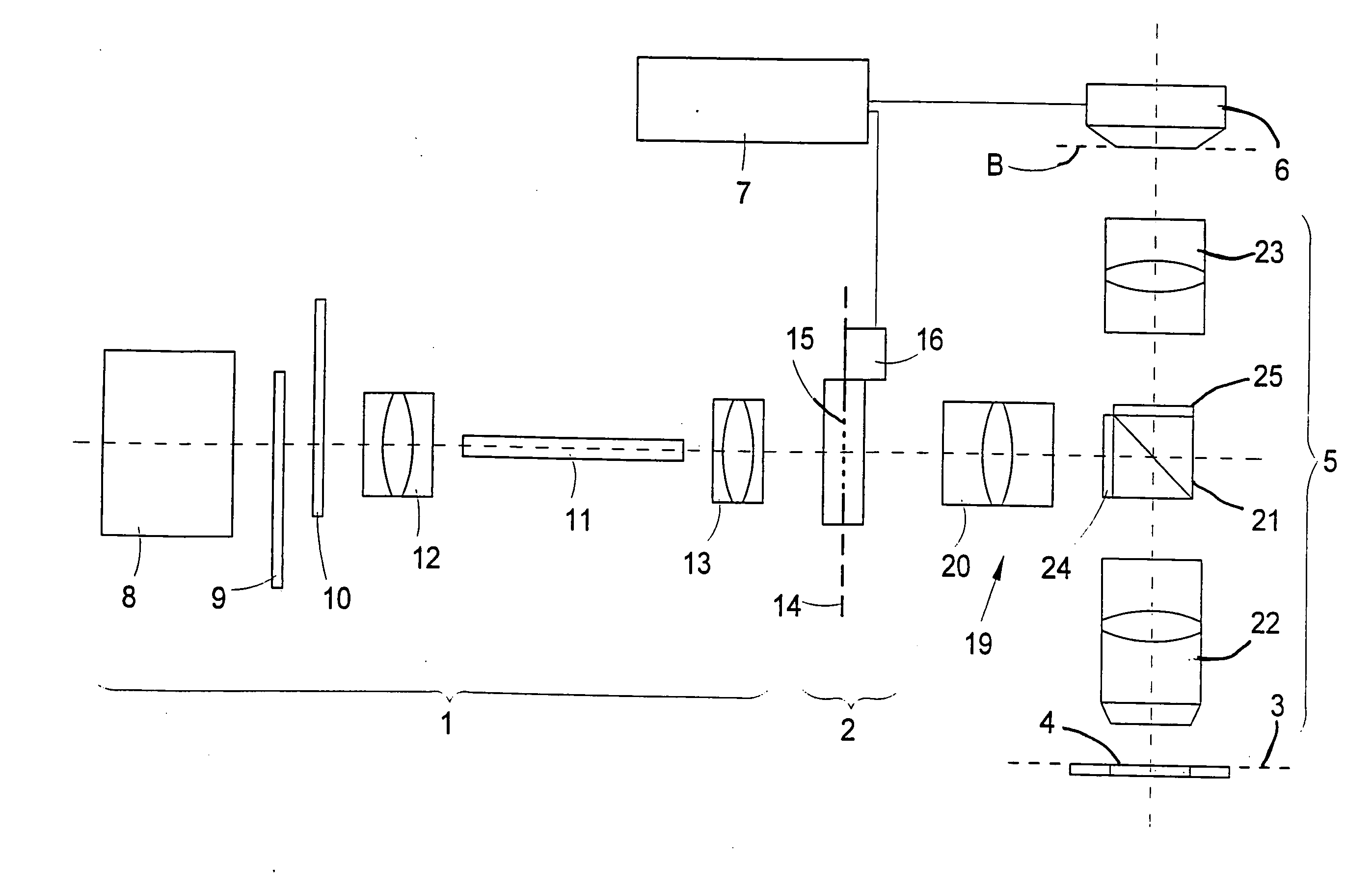
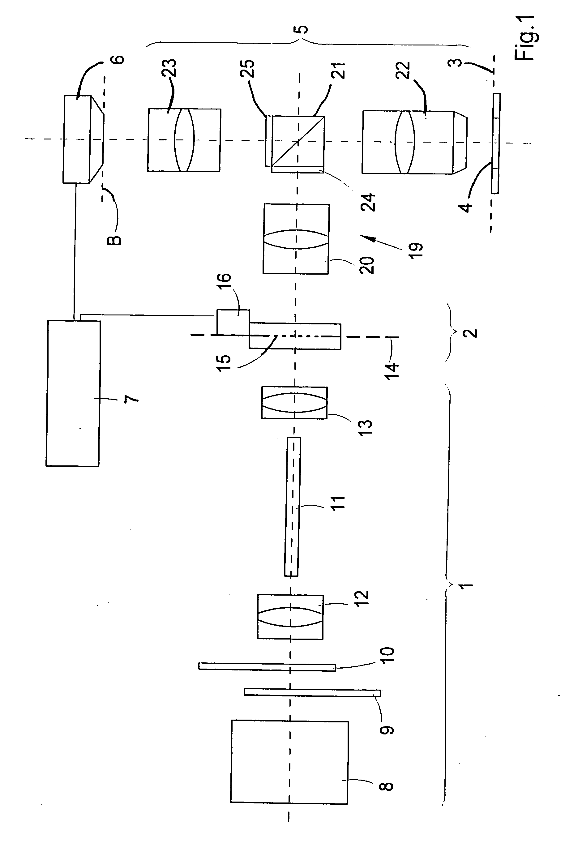
[0061]FIG. 1 shows an arrangement for detecting an image of a heterogeneous luminescing or illuminated broad surface object wherein stray light influences are suppressed. The arrangement of FIG. 1 is a first preferred embodiment of the invention and includes an illumination unit 1, a unit 2 for generating illumination patterns in an object plane 3 of an object 4 arranged on a carrier or table. The unit 2 is mounted downstream of the illumination unit 1 and the arrangement further includes an imaging optic 5 for imaging the object 4 on an image plane B and a position resolving detector 6 arranged in the image plane. An evaluation unit 7 is connected via a detector connection to the detector 6 and via a control line to the unit 2.

[0062] The illumination unit 1 includes a light or radiation source 8. The following are arranged downstream of the source 8: a filter 9, a shutter 10, elements 11 and first illumination optics 12 and 13 for homogeneously illuminating a region of a field dia...


PUM


Abstract

A method images an object (4) by means of a wide field optic onto a position resolving detector (6) for optical radiation with suppression of stray light. In this method, the object (4) is illuminated in at least one object plane (3) with at least two illumination patterns (26, 27) and corresponding images are detected for each of the illumination patterns (26, 27). The illumination patterns (26, 27) each have bright regions (26; 33; 37) and dark regions (27) in the object plane (3). When there is a superposition of the illumination patterns (26, 27) in the optic plane (3), the object (4) is completely covered. A dark image of the object is determined from the detected images. A bright image of the object (4) is generated and the dark image is subtracted from the bright image.

Description

CROSS REFERENCE TO RELATED APPLICATION [0001] This application claims priority of German patent application no. 10 2004 053 730.5, filed Nov. 6, 2004, the entire content of which is incorporated herein by reference. FIELD OF THE INVENTION [0002] The invention relates to a method for imaging an object by means of a wide field optic onto a position-resolving detector for optical radiation with suppression of stray light as well as to an arrangement for carrying out the method. BACKGROUND OF THE INVENTION [0003] Biological specimens or materials are often investigated microscopically. Appropriate objects can especially be investigated with wide field optics which image the object or a plane of the object onto a position-resolving detector. The investigation can, for example, take place with conventional microscopy or fluorescence microscopy, especially quantitative fluorescence microscopy. The objects can especially be biochips which were produced with photolithographic techniques or b...

Claims


Application Information

Patent Timeline
Patent Type & Authority Applications(United States)
IPC IPC(8): G06K9/40
CPCG02B21/125G02B21/16
Inventor WESTPHAL, PETER
Owner CARL ZEISS SMT GMBH
Why Eureka
Try Eureka