Glass melting gurnace and method for producing glass

a glass melting furnace and glass technology, applied in glass pressing apparatus, glass making apparatus, manufacturing tools, etc., can solve the problems of affecting factors, affecting the efficiency of homogenizing molten glass, and limiting the melting furnace, so as to achieve stable quality, easy to introduce helium or neon, and easy to adjust the volume of molten glass introducing.

Inactive Publication Date: 2006-05-18
NIPPON ELECTRIC GLASS CO LTD
View PDF6 Cites 50 Cited by
  • Summary
  • Abstract
  • Description
  • Claims
  • Application Information

AI Technical Summary

Benefits of technology

[0014] A technique of accelerating deaeration of bubbles from the molten glass by applying a pressure reducing technique or vacuum technique to the molten glass at high temperatures involves removal of bubbles from the molten glass and easy partial loss of molten glass components through vaporization at the same time. Thus, environmental problems associated with collection of the molten glass components and problems such as degradation of the device itself by vaporized substances are pointed out. Further, a large device is required for treating a large volume of molten glass, but precise maintenance of a reduced pressure or vacuum environment involves problems in that precise and continual maintenance is required.
[0093] (17) The method of manufacturing glass of the present invention allows rapid and efficient diffusion and mixing, and dissolution of helium and / or neon into the molten glass.

Problems solved by technology

However, the melting furnaces are subjected to restrictions by various factors such as use, a production, a glass material, and a glass raw material, and are far from melting furnaces capable of homogenizing molten glass efficiently.
Even if optimal selections of the factors are made once, there are disadvantages in that the factors are apt to be affected by a glass flow rate, a melting temperature, a melting atmosphere, and the like.
Stirring through bubbling employing a bubbling nozzle or stirring with a stirrer is often combined with other methods, and the use of stirring alone leaves concerns.
The stirring method is rather useful means for aiding a deaeration effect by the above-described fining agents and an auxiliary method for enhancing the effect in combined use with other methods, and has not yet reached a level of realizing large effects in use of the method alone.
Thus, environmental problems associated with collection of the molten glass components and problems such as degradation of the device itself by vaporized substances are pointed out.
Further, a large device is required for treating a large volume of molten glass, but precise maintenance of a reduced pressure or vacuum environment involves problems in that precise and continual maintenance is required.

Method used


Image

  • Glass melting gurnace and method for producing glass
  • Glass melting gurnace and method for producing glass
  • Glass melting gurnace and method for producing glass

Examples


embodiment 1

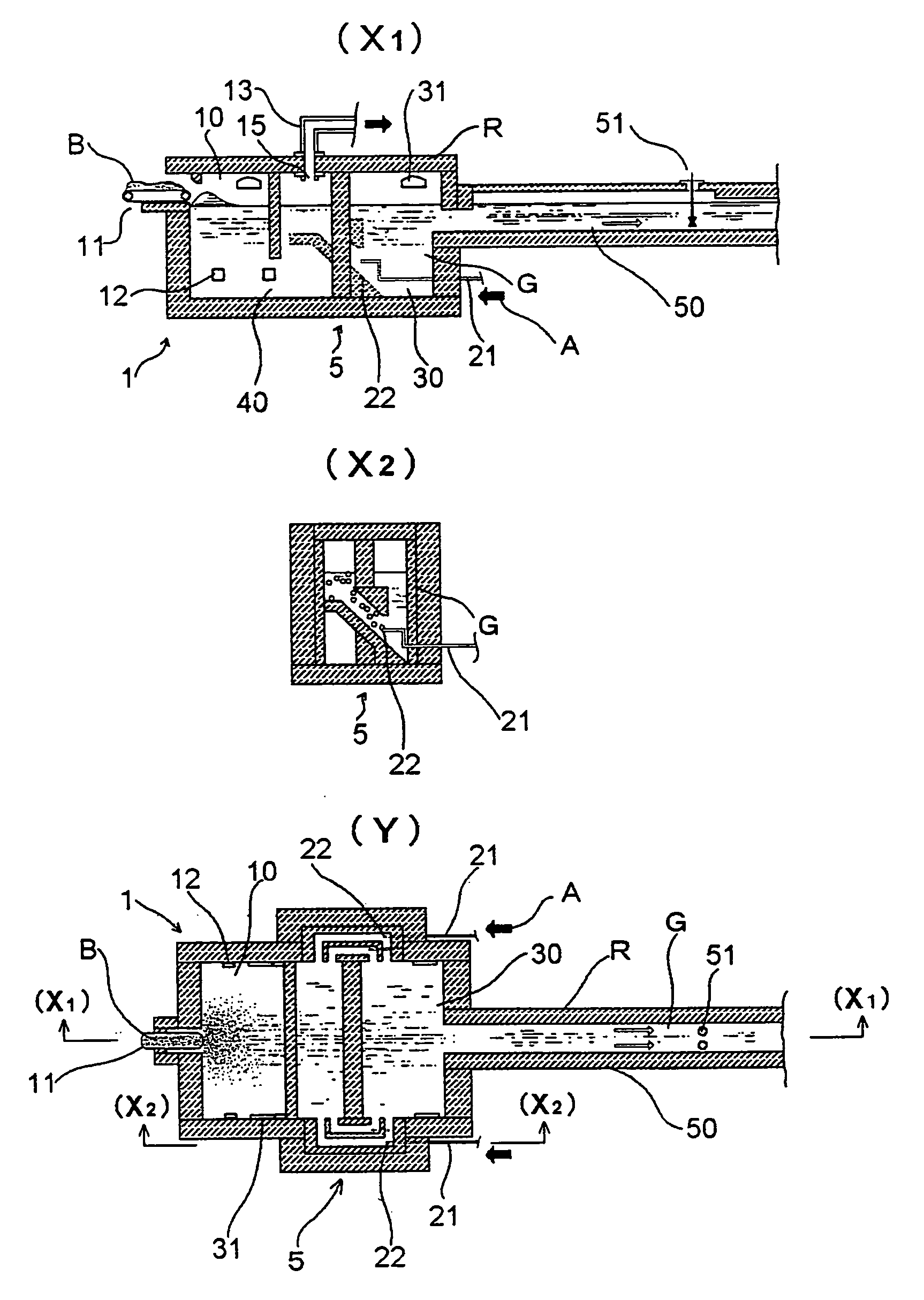
[0107] The inventors of the present invention have attempted to improve product yield than before by: applying the glass melting furnace of the present invention as a melting device for a glass product, which is silicate glass of a composition having an alkali content of 10 mass % or less and used as sheet glass for electronic components; and assuredly performing fining of the glass. The glass melting furnace of the present invention was realized by providing a noble gas dissolving device as noble gas dissolving means for diffusing and mixing, and dissolving helium and / or neon into molten glass, between a melting tank and fining chamber of a small continuous melting furnace conventionally used. FIG. 1 shows a constitution of a glass melting furnace 1. A refractory wall is provided between a melting tank 10 and a fining chamber 30. Molten glass G in the melting tank 10 flows into the fining chamber 30 through two noble gas dissolving devices 5 {see FIG. 1(Y)} respectively connected t...

embodiment 2

[0112] Next, an embodiment employing a constitution suitable for melting a glass material having easier properties of diffusion and mixing, and dissolution of helium and / or neon into the molten glass compared with Embodiment 1 as a glass melting furnace for tubular glass used for electronic components is described.

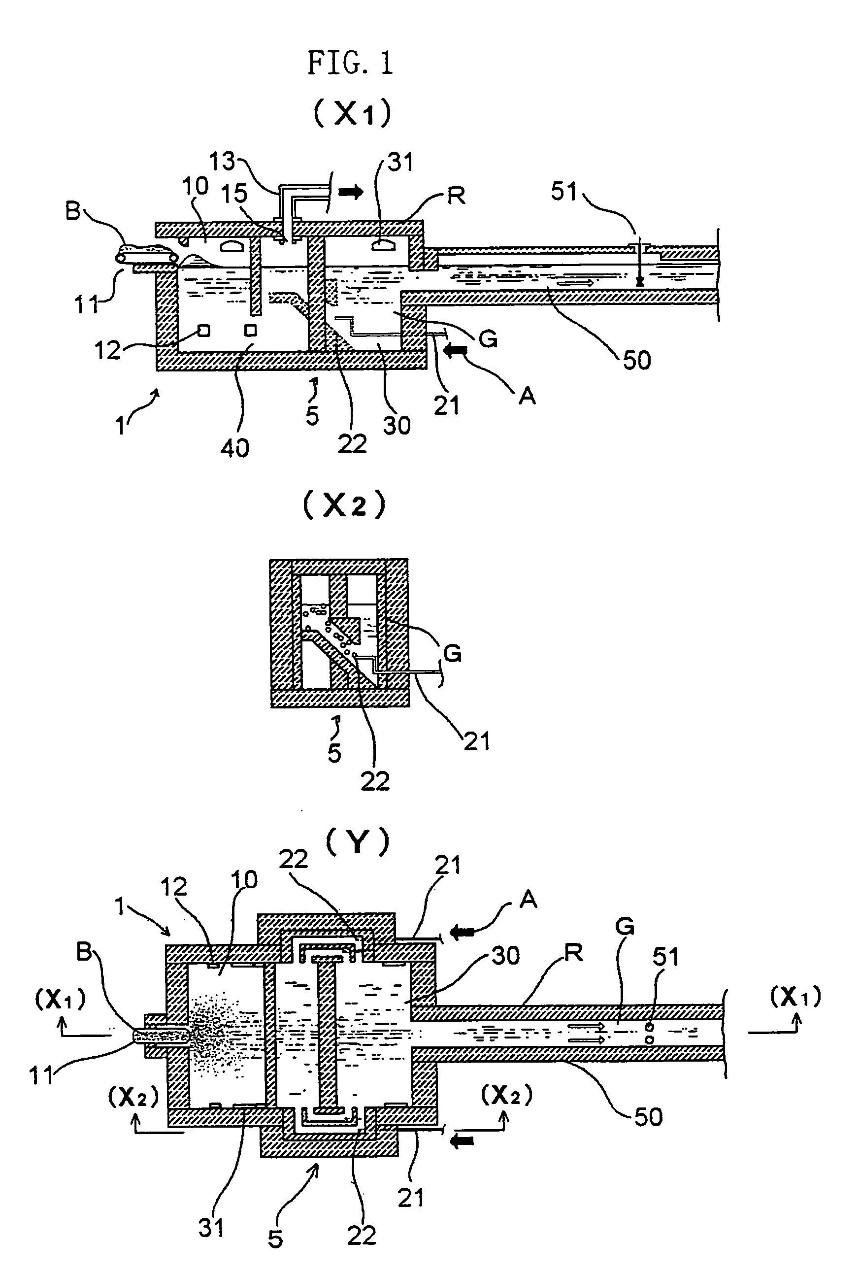
[0113] The melting furnace is very small as a continuous melting furnace, and has a disadvantage that unreacted raw material components are apt to flow out to the fining chamber because of a small volume of the melting tank. In order to overcome the disadvantage, the melting furnace employs a structure having a noble gas dissolving device connected downstream of the melting tank. FIG. 2 shows a partially sectional view of a noble gas dissolving device 6 employed in the glass melting furnace.

[0114] The molten glass G melted in the melting tank flows into the noble gas dissolving device 6 from the left side of FIG. 2. Meanwhile, the helium gas A is introduced in an opposit...

embodiment 3

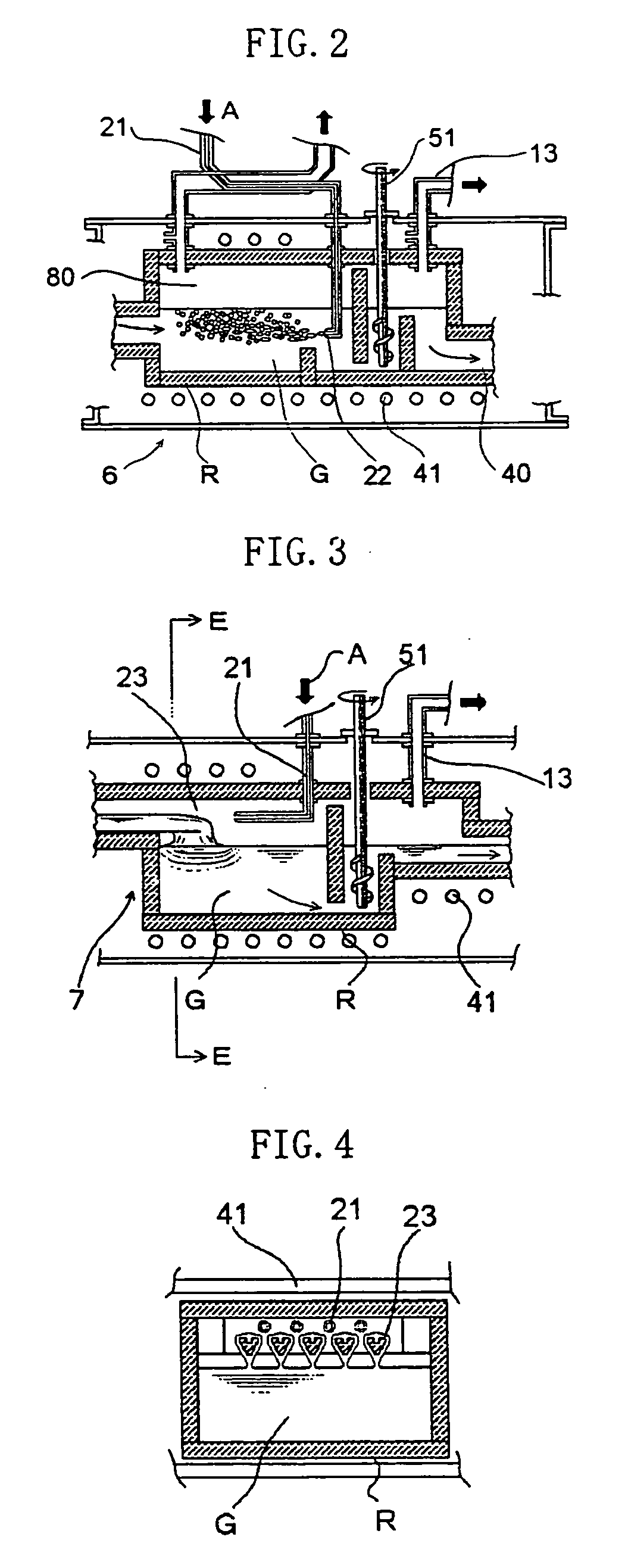
[0118] Next, an embodiment employing a glass melting furnace of the present invention as an apparatus for manufacturing display glass is described. Because bubbles in an image display part are highly visible, glass products used for such an application require stricter management of bubble quality than that of glass products used for other applications, and bubbles are perceived as critical defects. FIG. 3 shows a longitudinal sectional view of a noble gas dissolving device 7 provided in the glass melting furnace of the present invention, and FIG. 4 shows a transverse sectional view of the E part of FIG. 3. The raw materials charged into the melting tank are melted by heating with a burner and by direct heating with a platinum electrode, and the molten glass G flows into the noble gas dissolving device 7 from the left side of FIG. 3. As shown in FIGS. 3 and 4, heat resistant tubs 23 are provided inside the noble gas dissolving device 7. While the molten glass G flows along the heat ...


PUM

PropertyMeasurementUnit
vector angleaaaaaaaaaa

Abstract

A charged glass raw material B is melted in a melting tank 10 by heating with a burner 31 and by heating with electrodes 12, to form molten glass G. Then, the molten glass G flows into a tank additionally provided as a noble gas dissolving tank 20 through a throat 40. The noble gas dissolving tank 20 is provided with a noble gas dissolving device 53, and the noble gas dissolving device 53 is provided with sixteen noble gas inlets 22 for introducing a helium or neon gas supplied to a hearth through heat resistant gas introduction tubes 21 into the noble gas dissolving tank 20. Bubbles of a helium gas A having a purity of 99% are blown out from the noble gas inlets 22 in volumes such that the bubbles have an average diameter of 80 mm or less in the molten glass G.

Description

TECHNICAL FIELD [0001] The present invention relates to a glass melting furnace capable of improving homogeneity of a glass product by reducing bubble defects in glass, and to a method of manufacturing glass using the glass melting furnace. BACKGROUND ART [0002] Over many years, glass manufacturing industry has aimed at manufacturing homogeneous glass products containing no contaminants, bubbles, and the like through melting at high efficiency, and supplying glass products that meet demands. The glass manufacturing industry has attempted to attain an object of manufacturing homogeneous glass in various glass products, and numerous inventions have been made to attain the object. Although factors causing inhomogeneous glass such as stones, cords, and precipitation of heterogeneous crystals in glass can be eliminated, an object of removing bubbles completely remains unattained. The removal of bubbles generally employs a method involving: addition of fining agents in a raw material comp...

Claims


Application Information

Patent Timeline
Patent Type & Authority Applications(United States)
IPC IPC(8): C03B5/225C03B5/193C03B5/187
CPCC03B5/187C03B2201/20C03B5/225C03B5/193Y02P40/57
Inventor TAKAGI, MASATAKAYOSHIDA, NORIYUKIAKIMOTO, TAKAMASATAKAYA, TATUYA
Owner NIPPON ELECTRIC GLASS CO LTD
Why Eureka
Try Eureka