Method for producing the photoelectrode of a solar cell

a solar cell and photoelectrode technology, applied in the direction of electrolytic capacitors, pv power plants, solid-state devices, etc., can solve the problems of poor conductivity of polymer hole conductors or high viscosity electrolytes recently in use, and achieve the effects of increasing the generatable photocurrent, increasing the conductivity of electrolytes, and increasing light absorption

Inactive Publication Date: 2006-05-18
FRAUNHOFER GESELLSCHAFT ZUR FOERDERUNG DER ANGEWANDTEN FORSCHUNG EV +1
View PDF5 Cites 15 Cited by
  • Summary
  • Abstract
  • Description
  • Claims
  • Application Information

AI Technical Summary

Benefits of technology

[0009] Thus with the present method elongated cavities are produced in the nanoporous semiconductor layer, which as conducting channels increase the conductivity of the electrolyte or of the polymer hole conductor in the nanoporous layer. As sufficient diffusion plays especially in highly viscous electrolytes or polymer hole conductors a significant role for the function of the solar cell, in particular the contact of the redox pair to the semiconductor material, the present method increases the generatable photocurrent and in the same manner the bulk factor of the solar cell. This permits using highly viscous electrolytes or polymer hole conductors, in particular gel-like electrolytes or ionic fluids as electrolytes, also in solar cells with nanoporous photoelectrodes built in this manner.
[0010] Another advantage of the present method and of the corresponding solar cell is that adding cavities forms scattering centers in the photoelectrode. The scattering centers increase absorption of the light in the photoelectrode in particular by a dye located in the nanopores on the semiconductor material. The present method therefore results in increased conversion efficiency of a dye solar cell.
[0011] In the present method, the elongated particles are pr...

Problems solved by technology

Sufficiently fluid electrolytes have good conductivity, whereas the highly visco...

Method used


Image

  • Method for producing the photoelectrode of a solar cell
  • Method for producing the photoelectrode of a solar cell
  • Method for producing the photoelectrode of a solar cell

Examples


Embodiment Construction

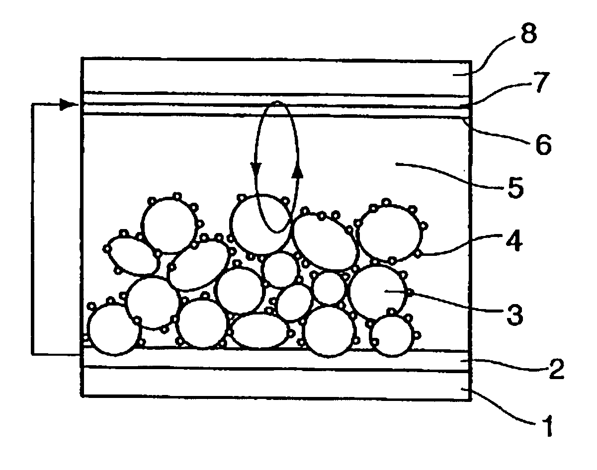
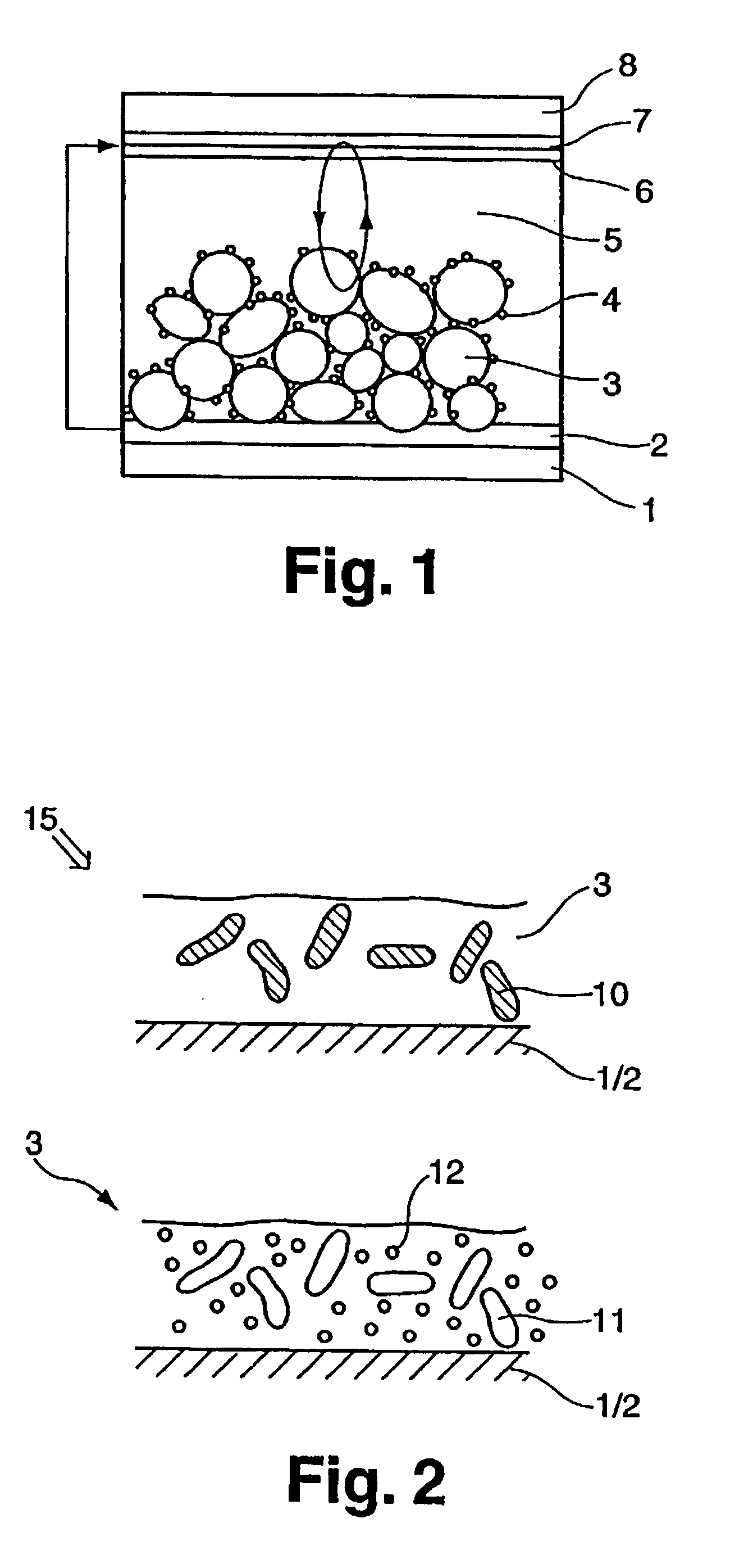
[0019]FIG. 1 shows the typical build-up of a dye solar cell as it can also be built according to the present invention. The solar cell is delimited on both sides by two glass substrates 1,8, at the inner sides of each a layer 2,7 of F:SnO2 is applied. The layer 3 of semiconductor material, in the present example TiO2, is applied on one of these layers. The cavities generated according to the present method are not shown in the FIGURE. The single nanocrystalline particles of the semiconductor material of layer 3 are coated with a dye 4.

[0020] The photoelectrode of the solar cell is formed by the thin layer 3 of the semiconductor material. The counter electrode comprises a platinum coating 6 on the layer 7. Between the photoelectrode and the counter electrode is the I− / I3− electrolyte 5. The process of generating the photocurrent by oxidation of the dye 4 while donating electrons to the conduction band of the semiconductor material (TiO2) and the return of the electrons via the red...


PUM


Abstract

The invention relates to a method for producing the photoelectrode of a solar cell in which a layer of a nanocrystalline semiconductor material is applied on a substrate and then sintered at a sintering temperature. In the method, elongated particles which burn out at the sintering temperature and leave elongated cavities in the layer are introduced into the layer. The invention also relates to a solar cell having a photoelectrode which has such type cavities. The method permits producing photoelectrodes for dye solar cells which allow sufficient diffusion of the electrolyte into the photoelectrode and thus a sufficiently great photocurrent even in the case of high viscous electrolytes.

Description

FIELD OF INVENTION [0001] The present invention relates to a method for producing the photoelectrode of a solar cell in which a layer of a nanocrystalline semiconductor material is applied to a substrate and then sintered at a sintering temperature. The present invention also relates to a solar cell having a photoelectrode which is producible according to the present method. [0002] The main field of application of the present method is the field of dye-sensitized solar cells. The photoelectrode of such a type dye solar cell is formed from a porous layer of nanocrystalline semiconductor material which is coated with a dye, for example an organic metal ruthenium dye which strongly absorbs the incident light. The photo-excitation of the dye leads to injecting electrons into the conduction band of the semiconductor material, for example TiO2. The dye oxidized in this manner takes up the missing electrons from the ions of the electrolyte or from a polymer hole conductor placed between th...

Claims


Application Information

Patent Timeline
IPC IPC(8): H01L25/00
CPCH01G9/2031H01L51/447Y02E10/542H10K30/87
Inventor KERN, RAINERNITZ, PETERHORE, SARMIMALA
Owner FRAUNHOFER GESELLSCHAFT ZUR FOERDERUNG DER ANGEWANDTEN FORSCHUNG EV
Why Eureka
Try Eureka