Methods for making composite tiles

a composite tile and tile technology, applied in the direction of lamination, building components, decorative arts, etc., can solve the problems of increased labor, increased cost, and increased skill required for laying

Inactive Publication Date: 2006-05-25
BOSERIO BRIAN AUGUSTINE
View PDF17 Cites 38 Cited by
  • Summary
  • Abstract
  • Description
  • Claims
  • Application Information

AI Technical Summary

Benefits of technology

[0069] Preferably, the pattern is that of a stencil and the stencil can be located within a mould. In this way, inexperienced stonemason can mark, cut and arrange stone elements according to complex patterns.

Problems solved by technology

A disadvantage with this laying method is that considerable skill is required to lay the stone elements such that a level finish is obtained, particularly when the stone elements are of small size.
Crazy paving when installed by a skilled stonemason can cost in excess of $200.00 per square metre.
Even greater skill is required and greater costs incurred if the elements themselves are of different shapes and sizes and a complex pattern is to be laid.
Another disadvantage with the traditional laying method is that it is not usually possible to obtain differences in mortar colouring over the whole job, and such variation in mortar colouring may be desired for aesthetic reasons.
A still further disadvantage is that it is effectively impossible to utilize these traditional methods in forming decorative stone finishes on vertical surfaces.
Although generally suitable for its intended purpose, this method of manufacturing “crazy paving” tiles suffered from two major disadvantages.
Firstly, it was difficult to maintain an even paving surface due to variations in thickness both within a tile element and also between adjacent tiles of other tile elements.
Secondly, but more importantly, the major problem with these tiles was that even when grouted, the linear intersections between adjacent tiles were clearly visible which prevent the natural look of crazy paving installed by a stonemason.
Not only was this a very labour intensive process in the cutting and calibration steps, the thickness variations between adjacent tile elements when laid could vary substantially with a consequent risk of tripping pedestrians walking thereover.

Method used


Image

  • Methods for making composite tiles
  • Methods for making composite tiles
  • Methods for making composite tiles

Examples


Embodiment Construction

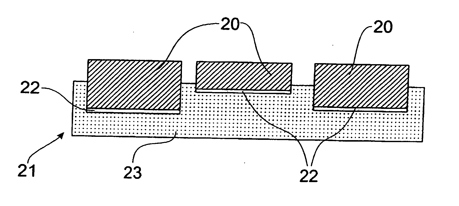
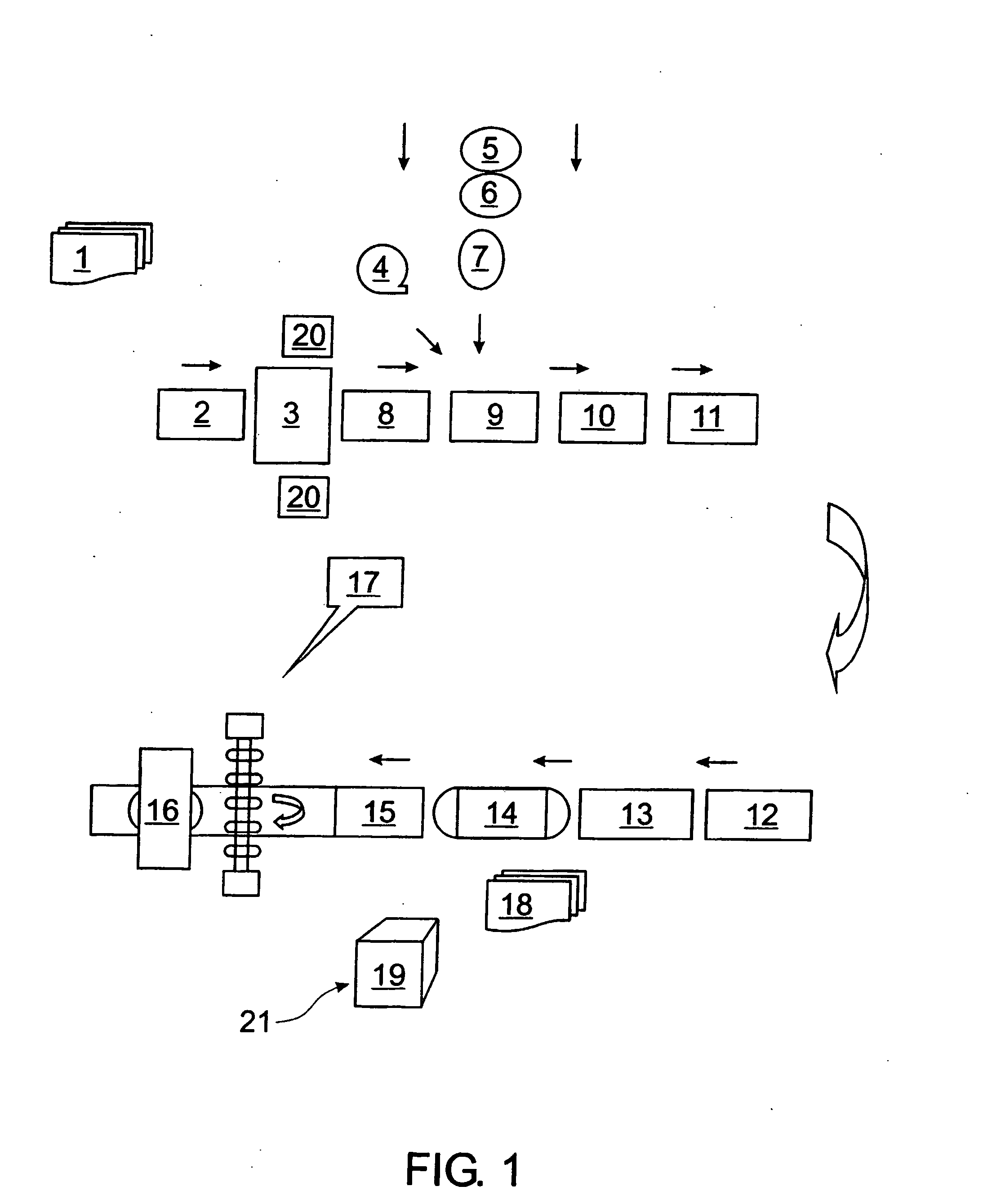
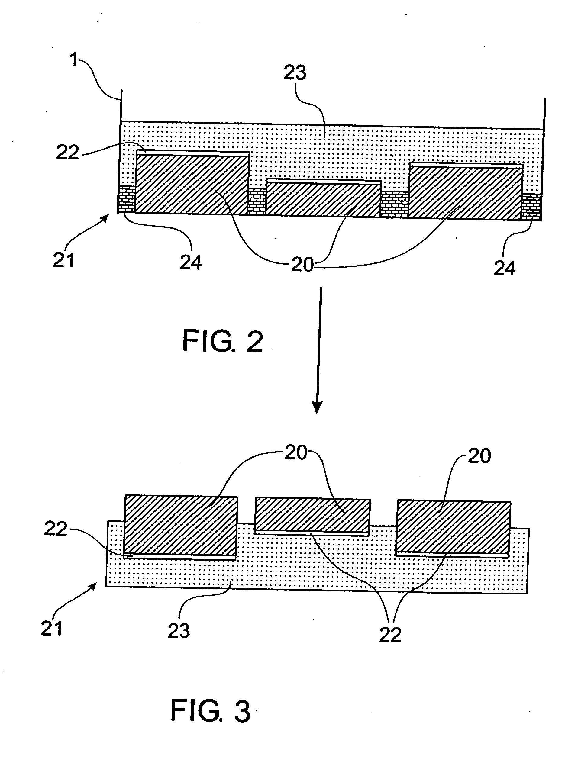
[0120]FIG. 1 is a flow diagram representing the steps in manufacturing an ungrouted composite tile, such as the tile 21 shown in FIGS. 2 and 3. Numerals 2-19 are shown only in FIG. 1.

[0121] A shallow mould or pan 1, having a base area of 500 mm×500 mm is placed on a conveyor belt 2 sprayed with a release agent such as form oil and transported to a layup station 3. Once the pan 1 reaches the layup station 3, stone elements (such as slate) 20 are arranged within the pan 1 to achieve a random pattern.

[0122] The stone elements 20 may either be cut to size but preferably randomly shaped fragments of stone are simply fitted into the pan 1 to achieve a random pattern. The stone elements 20 are spaced slightly apart from one another, and the preferred face of each stone element 20 is placed face down within the pan 1.

[0123] Once the stone elements 20 have been arranged within the pan 1, the pan 1 is conveyed to an applicator 8 that adds an inert displacer 24, typically talcum powder or f...


PUM

PropertyMeasurementUnit
thicknessaaaaaaaaaa
shapeaaaaaaaaaa
shapesaaaaaaaaaa

Abstract

A decorative paving tile or panel comprises a plurality of irregularly shaped stone elements of the same or differing thickness embedded in a backing layer or base to form a tile or panel of the predetermined thickness wherein the normally exposed surfaces of said stone elements lie in a plane substantially parallel to a mounting surface of said backing layer or base. A flowable displacement material may be employed in the interstices between-adjacent stone elements and/or a boundary wall of a tile or panel mould to forma grouting channel. An irregular space between adjacent stone elements of adjacent tiles or panels allows the formation of an optically seamless tiled or panelled surface when grouted.

Description

FIELD OF THE INVENTION [0001] This invention relates to methods for making composite tiles. BACKGROUND OF THE INVENTION [0002] A traditional method of laying tiles, slate or the like (from hereon referred to as “stone elements”) entails spreading mortar over a surface to which the stone elements are to be applied and then pressing each stone element into the mortar by hand. This paving system is typically known as “crazy paving” where the stone elements have irregular shapes. A disadvantage with this laying method is that considerable skill is required to lay the stone elements such that a level finish is obtained, particularly when the stone elements are of small size. Crazy paving when installed by a skilled stonemason can cost in excess of $200.00 per square metre. Even greater skill is required and greater costs incurred if the elements themselves are of different shapes and sizes and a complex pattern is to be laid. [0003] Another disadvantage with the traditional laying method...

Claims


Application Information

Patent Timeline
Patent Type & Authority Applications(United States)
IPC IPC(8): B29C39/10B32B37/00B28B19/00B28B23/00B44C1/28E01C5/22E04F13/14
CPCB28B19/0053B28B23/0075B44C1/28E01C5/22E01C2201/04E04F13/147E04F2201/091E04F2201/096
Inventor BOSERIO, BRIAN AUGUSTINE
Owner BOSERIO BRIAN AUGUSTINE
Why Eureka
Try Eureka