System for correcting display device and method for correcting the same

a display device and display technology, applied in the field of display correction system, can solve the problems of deteriorating the yield of the display device, affecting the operation efficiency of the operator, and lcd device becoming a defective product, etc., and achieve the effect of uniform display

Inactive Publication Date: 2006-05-25
SEMICON ENERGY LAB CO LTD
View PDF16 Cites 13 Cited by
  • Summary
  • Abstract
  • Description
  • Claims
  • Application Information

AI Technical Summary

Benefits of technology

[0014] The object of the present invention is to solve the above problem. In the present invention, a liquid crystal display (LCD) device includes a memory device for storing correction contents of pixel, and correction is performed by storing into the memory device the correction contents obtained by an external camera device, so that uniform display can be performed.

Problems solved by technology

If a TFT having a defect is in an open state or a short circuit state, a defect pixel has a desired voltage or a voltage on the defect pixel is unstable, so that the pixel produces as a point defect on a panel.
Though a defect of a pixel TFT can be corrected, a nonuniform display due to variation of a liquid crystal material and a band nonuniformity produced by rubbing cannot be corrected, so that an LCD device becomes a defective product in many cases.
In accordance with an increase of the size, it is difficult to maintain uniform display, so that a yield of an LCD device is deteriorated.
Also, in a personal computer and a work station, since an operator continues to watch a display portion at a near position for a long period of time, nonuniform display is disagreeable for an operator and efficiency of the operator decreases, so that it is a claim subject from a user.

Method used


Image

  • System for correcting display device and method for correcting the same
  • System for correcting display device and method for correcting the same
  • System for correcting display device and method for correcting the same

Examples


embodiment 1

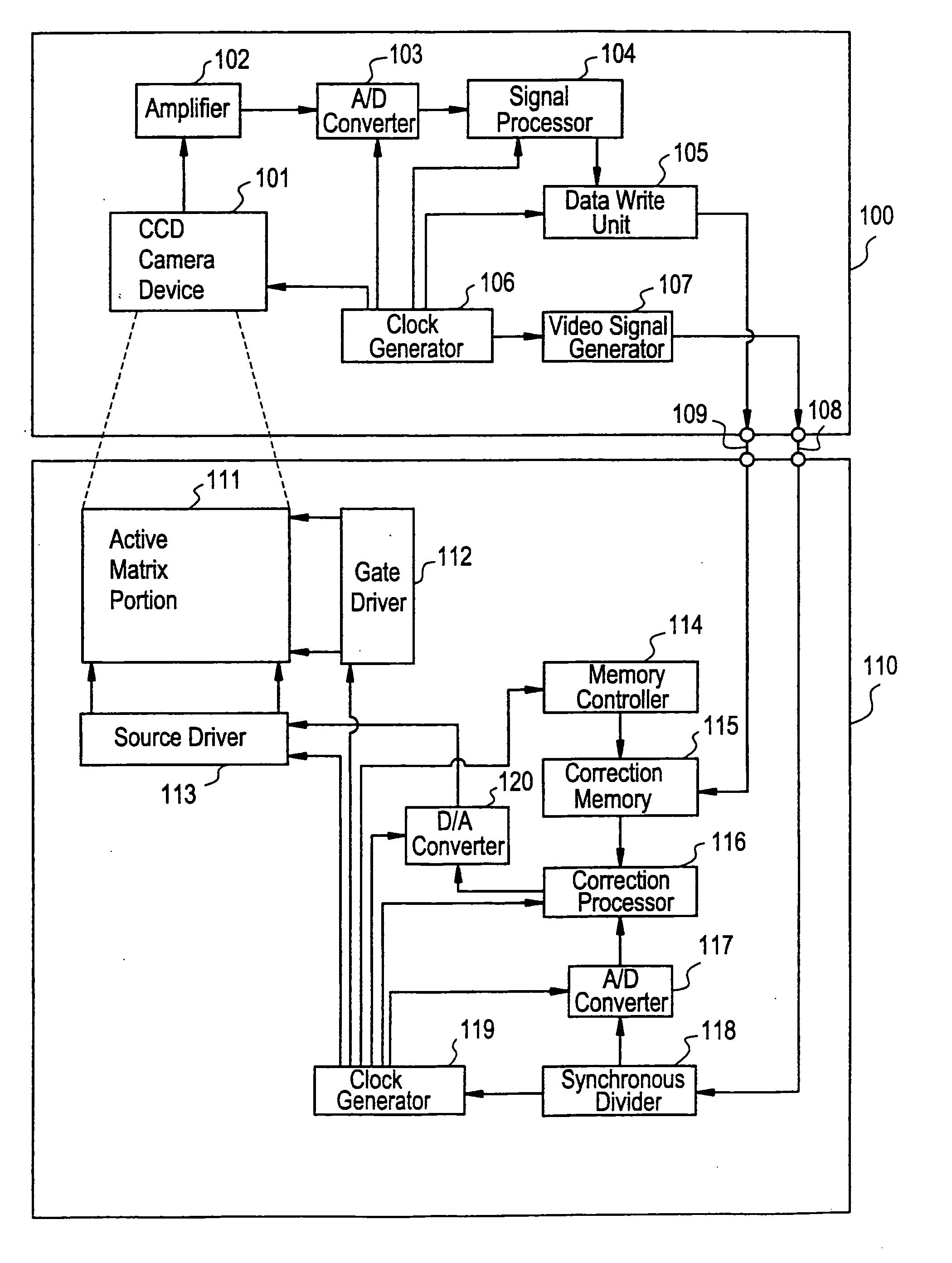
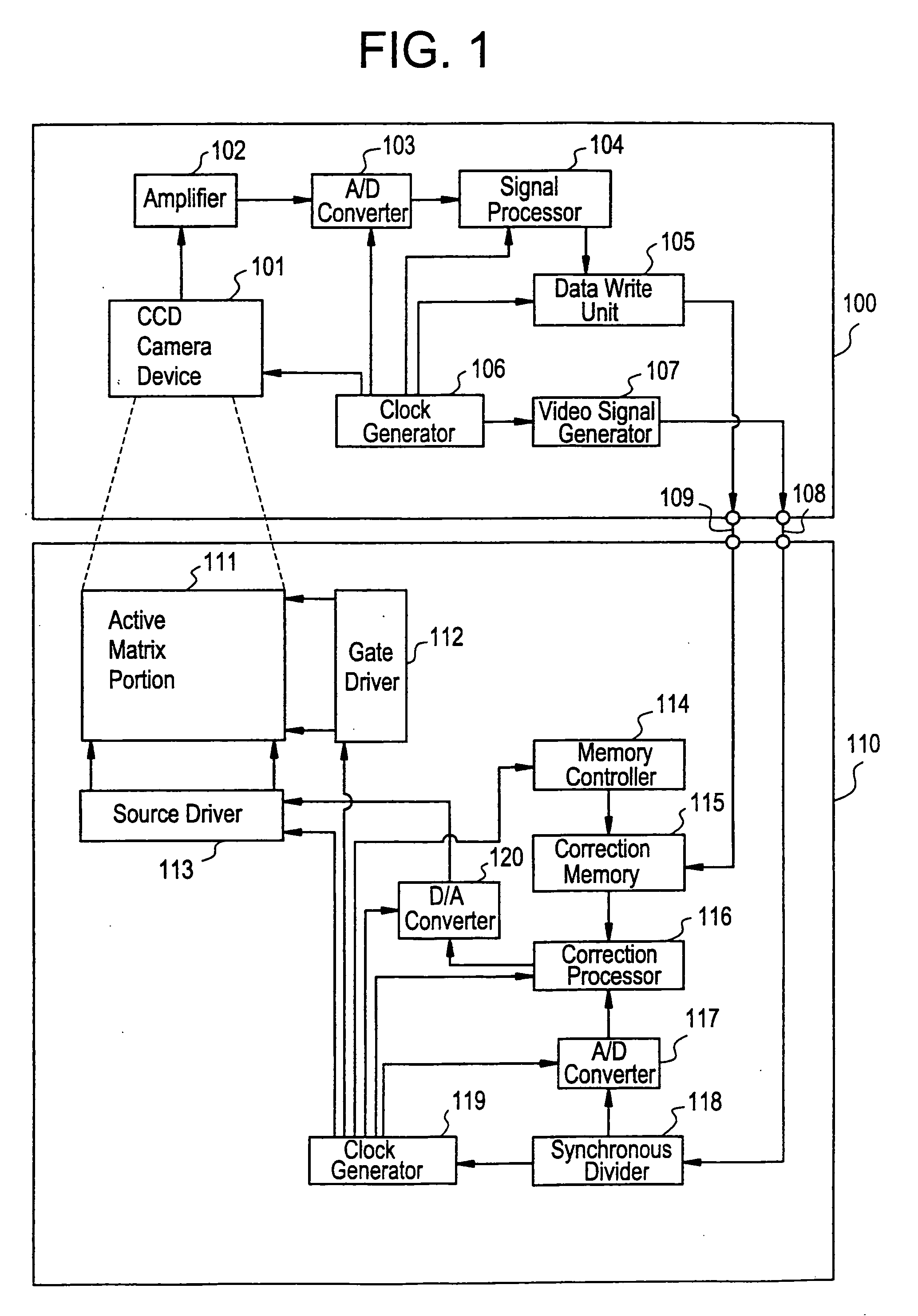
[0025]FIG. 1 shows a correction system having a liquid crystal display (LCD) device according to an embodiment of the present invention. In FIG. 1, the correction system includes an LCD device 110 formed on a glass substrate (not shown) and a correction information (correction data) producing device 100. The LCD device 110 has an active matrix portion 111, a gate driver 112, a source driver 113, a memory controller 114, a memory device (a correction memory 115), a correction processor 116, an analog / digital (A / D) converter 117, a synchronous divider 118, a clock generator 119 and a digital / analog (D / A) converter 120.

[0026] The correction information producing device 100 produces correction information used to correct the LCD device 110 and then writes the produced correction information into the correction memory 115. The device 100 has a charge coupled device (CCD) camera device 101, an amplifier 102, an A / D converter 103, a signal processor 104, a data write unit 105, a clock gen...

embodiment 2

[0049]FIG. 6 show a correction system having an LCD device according to another embodiment of the present invention. The embodiment is different from Embodiment 1, and obtainment and correction of display information to be displayed are performed a plurality of times.

[0050] In FIG. 6, a correction system of the embodiment includes an LCD device 620 formed on a glass substrate (not shown) and a correction information (correction data) producing device 600. The LCD device 620 has an active matrix portion 621, a gate driver 622, a source driver 623, a memory controller 624, a memory device (a correction memory 625), a correction processor 626, an A / D converter 627, a synchronous divider 628, a clock generator 629 and a D / A converter 630.

[0051] The correction information producing device 600 produces correction information used to correct the LCD device 620 and then writes the produced correction information into the correction memory 625. The device 600 has a CCD camera device 601, a...


PUM

PropertyMeasurementUnit
dielectric constantaaaaaaaaaa
ferroelectricaaaaaaaaaa
voltageaaaaaaaaaa

Abstract

In a display device having a nonvolatile memory device, such as an active matrix type liquid crystal display device, display contents displayed on the display device are obtained by a camera device. The obtained information (corresponding to the display contents) is digital-converted and then processed to detect a defect and a nonuniformity on the display device, so that correction information is produced. The correction information is stored in the nonvolatile memory device of the display device. Display information to be displayed on the display device is processed using the stored correction information, so that display contents are corrected and a defect and a nonuniformity on the display contents are inconspicuous.

Description

BACKGROUND OF THE INVENTION [0001] The present invention relates to a display correction system for a display device, in particular, a display device having a nonvolatile memory device and a display device correction method. [0002] As a conventional display device, a cathode ray tube (CRT) device, a plasma display device, a liquid crystal display (LCD) device or the like is used. Recently, an LCD device, in particular, an active matrix type LCD device has been developed. [0003] Since a dielectric constant of a liquid crystal substance (molecule) in a parallel direction to a molecule axis is different from that in a vertical direction, an LCD device uses this characteristic and displays ON / OFF states, that is, light / dark states by adjusting a transmission quantity or a scattering quantity of a light. In general, a liquid crystal material includes, a twisted nematic (TN) liquid crystal, a super twisted nematic (STN) liquid crystal, a ferroelectric liquid crystal and the like. [0004] I...

Claims


Application Information

Patent Timeline
Patent Type & Authority Applications(United States)
IPC IPC(8): G09G3/36G02F1/136G02F1/133G02F1/1368G09F9/00H04N5/21H04N5/66H04N17/04
CPCG09G3/006G09G3/3648G09G2320/02G09G2320/0233G09G2320/0285G09G2320/0693G09G2330/08G09G2330/10H04N5/21H04N5/66H04N17/04G09G2360/147Y10S345/904G09G3/36
Inventor KOYAMA, JUN
Owner SEMICON ENERGY LAB CO LTD
Why Eureka
Try Eureka