[0013] Incidentally, a printed board is available at relatively low cost and also has adaptability to
electrical connection between the surface deposited with the interconnect layer and the component side. However, the printed board is typically limited in interconnect pattern accuracy and the like to a range of about several 10 μm to several 100 μm. With consideration of accurate
coupling between optical elements and the optical wave-guide, the hybrid circuit substrate needs not only accurate alignment for the above
coupling as high as about several μm, but also a micro-fabricated interconnect pattern with increased accuracy. The hybrid circuit substrate has also posed a problem of a difficulty in employing the printed board for expected micro-fabrication of input / output pads of the semiconductor chips in future and / or
pitch reductions due to the increasing number of
bus interconnects with the increasing bandwidth between the semiconductor chips.
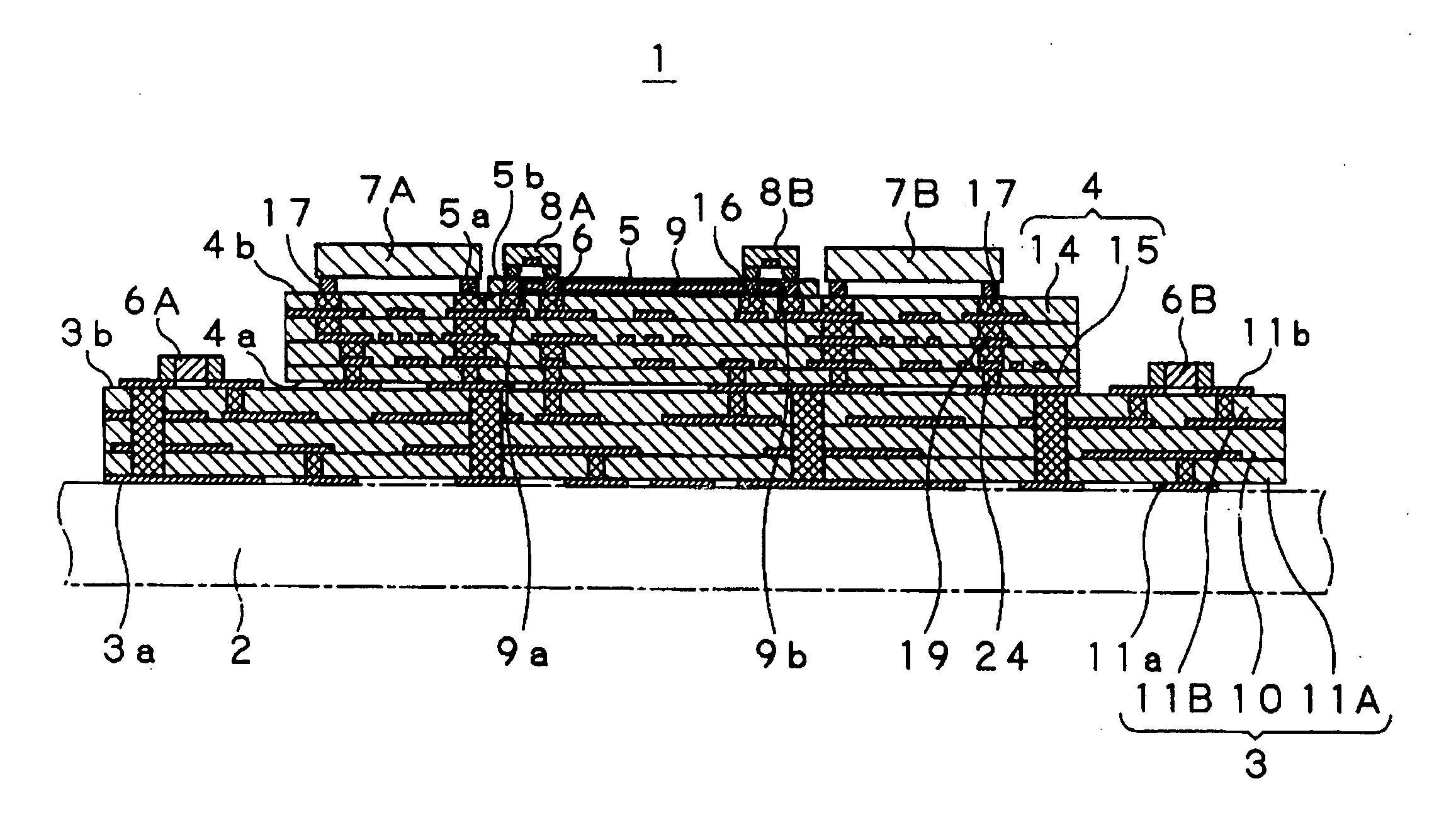
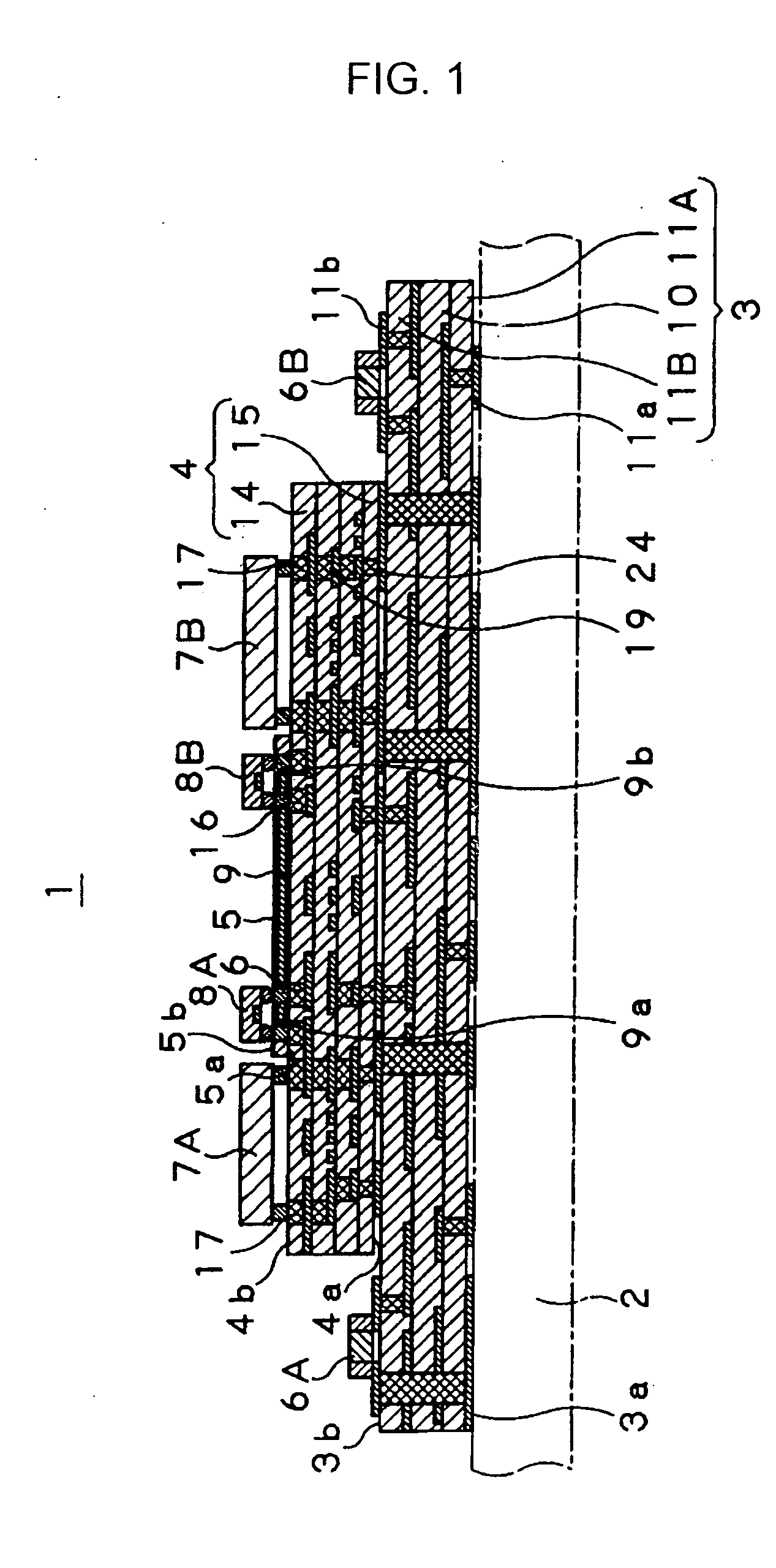
[0014] Accordingly, there is a need for a hybrid circuit substrate with optical and electrical interconnects embedded, more specifically, a hybrid circuit substrate, which is fabricated accurately at low cost, and ensures that high speed transmission with increased capacity of an information signal is achieved by enabling transmission of an electrical signal and a optical signal in such a way as to provide electrical and optical interconnects embedded. There is also a need for a method for manufacturing the above hybrid circuit substrate. There is further a need for a hybrid circuit module with optical and electrical interconnects embedded and also a method for manufacturing the above hybrid circuit module.
[0016] According to thus-configured hybrid circuit substrate with optical and electrical interconnects embedded in accordance with the preferred embodiment of the preferred embodiment of the present invention, the base substrate section fabricated at relatively low cost using the printed circuit process, the micro interconnect circuit section having the micro
electrical interconnect layer micro-fabricated with increased accuracy using the semiconductor process, and the
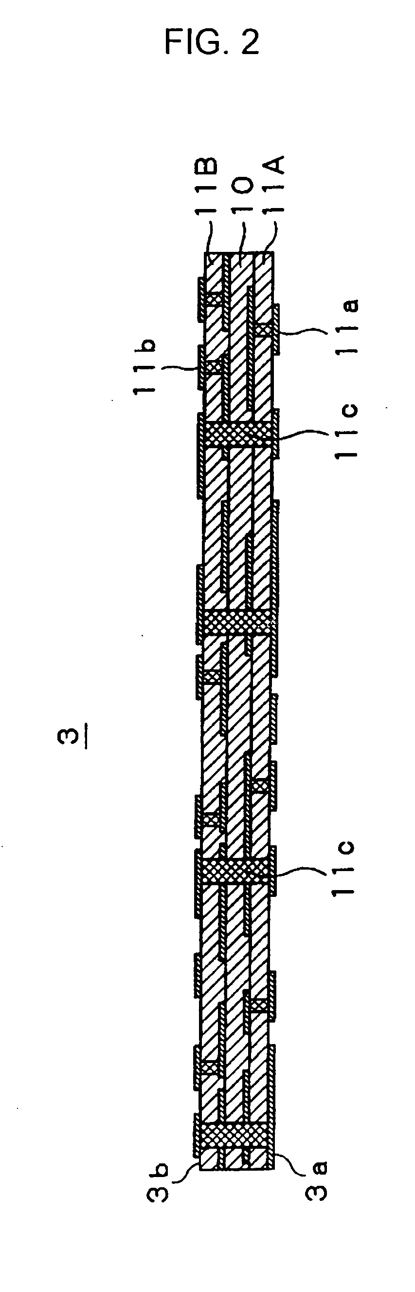
optical interconnect circuit section adaptable to high speed transmission with increased capacity of the information signal and the like using the optical wave-guide are stacked into a multi layer structure, which thus provides a low-cost hybrid circuit substrate having accurate optical and electrical interconnects that achieve high speed transmission with increased capacity of the information signal and the like. According to the preferred embodiment of the preferred embodiment of the present invention, the multi layer structure contributes toward form-factor reductions with electrical interconnect length reductions, and also ensures a sufficient packaging space for semiconductor chips and surface-mounted components and the like, so that multi-functionality or performance is increased. According to the preferred embodiment of the preferred embodiment of the present invention, a hybrid circuit substrate is provided, for instance, which has the advantages of providing the base substrate section having a power supply section and a
ground line respectively assembled in a
motherboard and the like with a sufficient area ensured, of providing the micro interconnect circuit section electrically connectable to the optical element and / or the semiconductor chips with accuracy and also being capable of deposition of high performance passive elements and the like, for instance, therein, of providing the optical interconnect circuit section having an accurate optical wave-guide and also being capable of accurate
coupling between the optical wave-guide and the optical element, and of being applicable to various characteristics in an optimal manner.
[0018] According to the method for manufacturing the hybrid circuit substrate with optical and electrical interconnects embedded in accordance with the preferred embodiment of the present invention having the above processes, a hybrid circuit substrate is manufactured, which is configured with a multi layer structure obtained by stacking the base substrate section fabricated at relatively low cost using the printed circuit process, the micro interconnect circuit section having the micro electrical interconnect layer micro-fabricated with increased accuracy using the semiconductor process and the optical interconnect circuit section adaptable to high speed transmission with increased capacity of the information signal and the like using the optical wave-guide. According to the preferred embodiment of the present invention, a low-cost hybrid circuit substrate may be manufactured, which has accurate optical and electrical interconnects that achieve high-speed transmission with increased capacity of the information signal and the like. According to the present invention, a hybrid circuit substrate may be manufactured, in which the multi layer structure obtained by stacking the above sections contributes toward form-factor reductions with electrical interconnect length reductions and also ensures a sufficient packaging space for semiconductor chips and surface-mounted components and the like, so that multi-functionality or performance is increased. According to the preferred embodiment of the present invention, a hybrid circuit substrate may be manufactured, for instance, which has the advantages of providing the base substrate section having a power supply section and a
ground line respectively assembled in a
motherboard and the like with a sufficient area ensured, of providing the micro interconnect circuit section electrically connectable to the optical element and / or the semiconductor chips with accuracy and also being capable of deposition of high performance passive elements and the like, for instance, therein, of providing the optical interconnect circuit section having an accurate optical wave-guide and also being capable of accurate coupling between the optical wave-guide and the optical element, and of being applicable to various characteristics in an optimal manner.
[0020] According to thus-configured hybrid circuit module with optical and electrical interconnects embedded in accordance with the preferred embodiment of the present invention, the base substrate section fabricated at relatively low cost using the printed circuit process, the micro interconnect circuit section having the micro electrical interconnect layer micro-fabricated with increased accuracy using the semiconductor process and the optical interconnect circuit section adaptable to high speed transmission with increased capacity of the information signal and the like using the optical wave-guide are stacked into a multi layer structure, which thus contributes toward form-factor reductions with electrical interconnect length reductions and also ensures a sufficient packaging space for semiconductor chips and surface-mounted components and the like, so that multi-functionality or performance is increased with high speed transmission with increased capacity of the information signal and the like. According to the preferred embodiment of the present invention, a high performance hybrid circuit module is provided, for instance, which has the advantages of providing the base substrate section having a power supply section and a
ground line respectively assembled in a motherboard and the like with a sufficient area ensured, of providing the micro interconnect circuit section electrically connectable to the optical element and / or the semiconductor chips with accuracy and also being capable of deposition of high performance passive elements and the like, for instance, therein, of providing the optical interconnect circuit section having an accurate optical wave-guide and also being capable of accurate coupling between the optical wave-guide and the optical element, and of being adaptable to accurate connection to the semiconductor chips and the surface-mounted components and the like in an optimal manner.
[0022] According to the method for manufacturing the hybrid circuit module with optical and electrical interconnects embedded in accordance with the preferred embodiment of the present invention having the above processes, a hybrid circuit module with optical and electrical interconnects embedded may be manufactured, which is configured with a multi layer structure obtained by stacking the micro interconnect circuit section and the optical interconnect circuit section on a base circuit section of the base substrate section fabricated at relatively low cost using the printed circuit process in such a way that the micro electrical interconnect layer micro-fabricated with increased accuracy using the semiconductor process and the optical element adaptable to high speed transmission with increased capacity of the information signal and the like using the optical wave-guide are electrically connected to the base circuit section, and that the
light emitting device is also electrically connected to the semiconductor chips and / or the surface
mount-type electronic components. According to the preferred embodiment of the present invention, a hybrid circuit module may be manufactured, which contributes toward form-factor reductions with electrical interconnect length reductions, and ensures a sufficient packaging space for semiconductor chips and surface-mounted components and the like, so that multi-functionality or performance is increased with high speed transmission with increased capacity of the information signal and the like. According to the preferred embodiment of the present invention, a high performance hybrid circuit module may be manufactured, for instance, which has the advantages of providing the base substrate section having a power supply section and a ground line respectively assembled in a motherboard and the like with a sufficient area ensured, of providing the micro interconnect circuit section electrically connectable to the optical element and / or the semiconductor chips with accuracy and also being capable of deposition of high performance passive elements and the like, for instance, therein, of providing the optical interconnect circuit section having an accurate optical wave-guide and also being capable of accurate coupling between the optical wave-guide and the optical element, and of being adaptable to accurate connection to the semiconductor chips and the surface-mounted components and the like in an optimal manner.

