Electrohydrodynamic spraying system

a spraying system and electrohydrodynamic technology, applied in the direction of liquid/solution decomposition chemical coating, superimposed coating process, light and heating apparatus, etc., can solve the problems of large film size, limited electrostatic force accumulation within liquid, and limited electrohydrodynamic spraying techniques, including clcb

Inactive Publication Date: 2006-05-25
THE BOARD OF TRUSTEES OF THE UNIV OF ILLINOIS
View PDF13 Cites 85 Cited by
  • Summary
  • Abstract
  • Description
  • Claims
  • Application Information

AI Technical Summary

Problems solved by technology

An electrohydrodynamic spraying apparatus applies a charging voltage to a liquid, resulting in an accumulation of repulsive electrostatic force within the liquid.
Electrohydrodynamic spraying techniques, including CLCB, typically have been limited to use with substrates having a surface area less than 10 square centimeters (cm2).
Electrostatic repulsion between nanodrops formed from an individual liquid jet can further contribute to the non-uniformity of the film, leading to an overall morphology of a ring made up of circular patches of nanodrops.
In addition to limiting the sizes of films produced, these disadvantages can also hinder the adjustment of an electrohydrodynamic spraying apparatus to accommodate different materials or applications.
For example, the distance between the spray nozzle and the substrate cannot be changed without affecting the morphology of the deposited nanodrops and the resulting thin film.

Method used


Image

  • Electrohydrodynamic spraying system
  • Electrohydrodynamic spraying system
  • Electrohydrodynamic spraying system

Examples


example 1

Two-Electrode Spray Apparatus

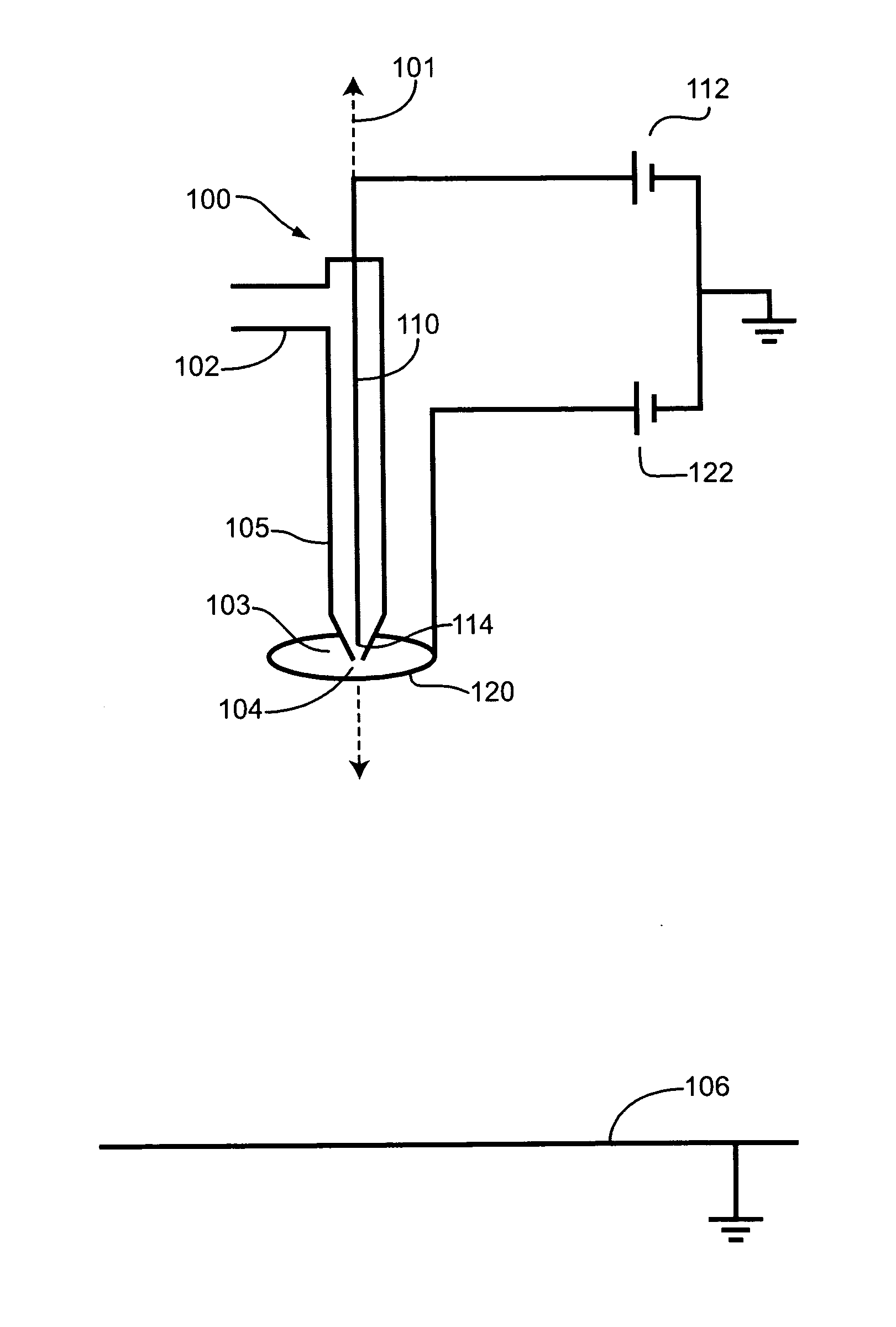
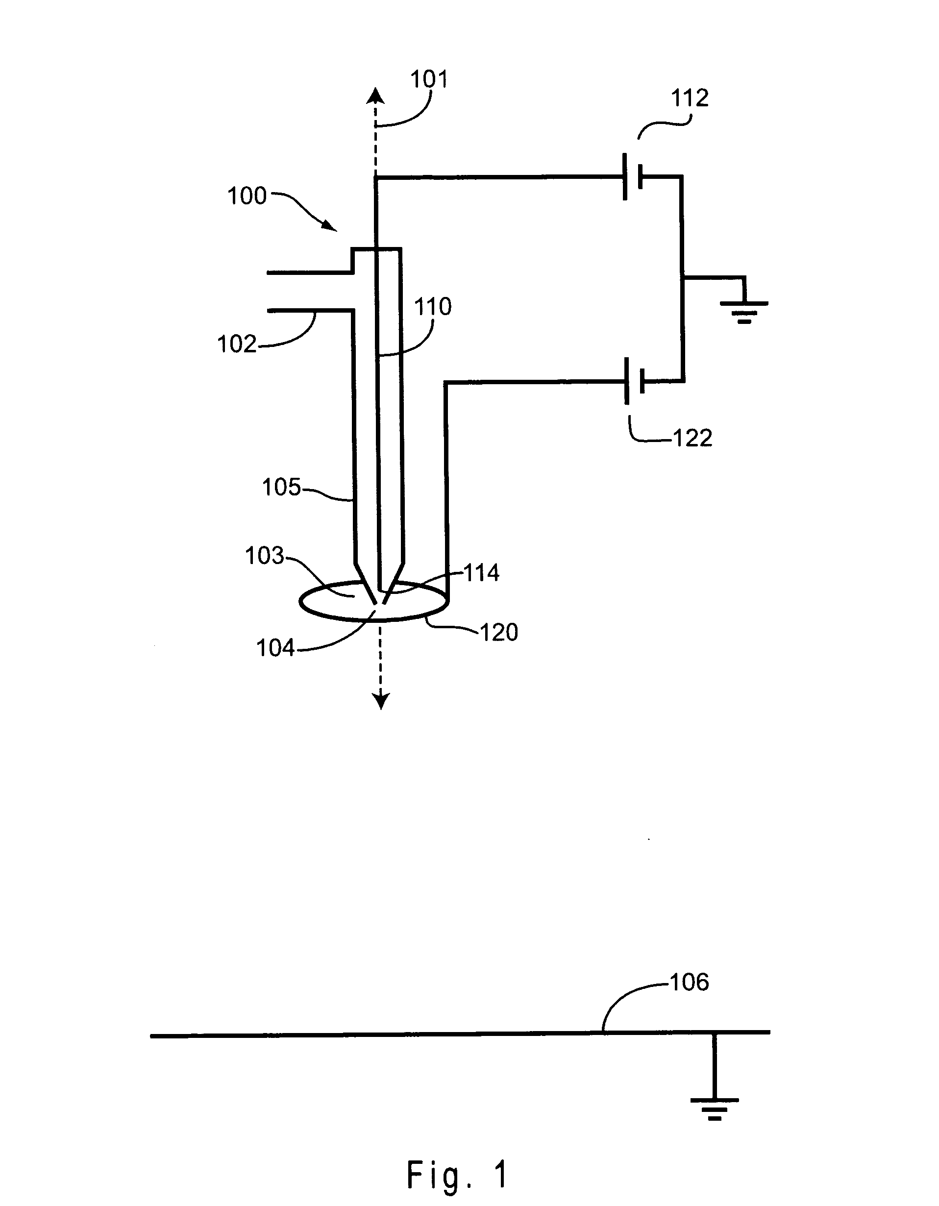
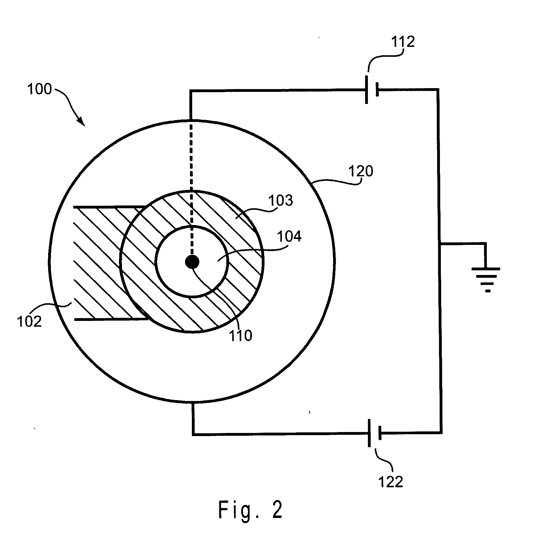
[0070] An electrohydrodynamic spraying system was constructed having a spray nozzle, an inner electrode, an outer electrode, and a substrate. The spray nozzle contained a liquid inlet and a tubular polypropylene portion. The substrate was positioned normal to the spray nozzle, and at a distance of 200 mm from the nozzle opening. Referring to FIG. 10, the inner diameter of the polypropylene tube 205 at its opening 206 downstream of the liquid inlet was 0.6 mm. At this downstream opening, a tubular, reducing glass insert 203 was stationed inside the polypropylene tube. The inner diameter of the reducing insert was 0.14 mm, and the length of the insert was 2 mm, with 1 mm of the insert in contact with the inner surface of the main tube. The downstream opening 204 of the reducing insert served as the opening for the nozzle 200. The inner electrode 210 was a tungsten needle, having a diameter of 125 microns and having a point 211 with a diameter of less than...

example 2

Variation of Voltage on Inner and Outer Electrodes

[0071] An electrohydrodynamic spraying system was used to spray a liquid mixture on a substrate. The liquid mixture contained a polymer mixture and a solvent mixture. The polymer mixture was a 1:20 blend of poly(3,4-ethylenedioxythiophene) and poly(styrenesulfonate), suspended in water at a 2.85 wt % solids content, available as BAYTRON P VP CH8000 (H.C. Starck; Newton, Mass.). The solvent mixture was 20:1 isopropyl alcohol and diethylene glycol, and the polymer was mixed with the solvent mixture for an overall composition of 1:20:1 of polymer mixture, isopropyl alcohol, and diethylene glycol. The liquid was passed through an electrohydrodynamic spray nozzle at a rate of 20 microliters per minute. The electrohydrodynamic spraying system was similar to that described in Example 1, except that the outer electrode was a ring having a diameter of 51 mm. The outer electrode was positioned 7.5 mm downstream of the nozzle opening. The subs...

example 3

Formation of Thin Film

[0073] An electrohydrodynamic spraying system was used to spray a liquid mixture on a substrate. The liquid mixture was identical to that used in Example 2. The liquid was passed through an electrohydrodynamic spray nozzle at a rate of 20 microliters per minute. The electrohydrodynamic spraying system was identical to that described in Example 1. The substrate was indium tin oxide (ITO) coated glass. A voltage of 20 kV was applied to the inner electrode, and a voltage of 12 kV was applied to the outer electrode.

[0074]FIG. 6 shows an SEM micrograph of a polymer film on the substrate, observed at an angle of 45 degrees. This film was deposited by spraying the liquid for 75 minutes. The outer electrode was positioned completely upstream of the nozzle opening, such that the distance between the downstream rim of the cup and the nozzle opening was 5.5 mm.

[0075]FIG. 7 shows an SEM micrograph of a polymer film on the substrate, observed at an angle of 45 degrees. T...


PUM

PropertyMeasurementUnit
distanceaaaaaaaaaa
distanceaaaaaaaaaa
distanceaaaaaaaaaa

Abstract

An electrohydrodynamic spray apparatus includes a liquid inlet and a spray nozzle in fluid communication with the liquid inlet, where the spray nozzle has an opening downstream of the liquid inlet. An inner electrode is situated at least partially inside the spray nozzle. An outer electrode is situated external to the spray nozzle and within about 100 mm of the opening of the nozzle. The electrohydrodynamic spray apparatus can be combined with a substrate to form an electrohydrodynamic spray system. The electrohydrodynamic spray apparatus or system can be used to form nanostructures such as nanodrops, nanoparticles and thin films.

Description

BACKGROUND [0001] Electrohydrodynamic spraying has been used to process liquids into structures having sizes on the micrometer and nanometer scale. An electrohydrodynamic spraying apparatus applies a charging voltage to a liquid, resulting in an accumulation of repulsive electrostatic force within the liquid. When the repulsive electrostatic force exceeds the surface tension force, the surface of the liquid is disrupted to form small jets of liquid. These small jets then break up into streams of charged liquid clusters, which are referred to as “nanodrops” when the dimensions of the clusters are on the order of 100 nanometers (nm) or less. [0002] Typically, nanodrops produced by electrohydrodynamic spraying are directed to the surface of a substrate material, which may be neutral or which may have an electric charge opposite that of the drops. If sufficient numbers of nanodrops accumulate on the substrate, the nanodrops will tend to coalesce and form a thin film. Nanodrops containin...

Claims


Application Information

Patent Timeline
Patent Type & Authority Applications(United States)
IPC IPC(8): B05C5/00B05D1/04B05B7/00
CPCB05B5/0255B05B5/0533
Inventor KIM, KYEKYOONSINGH, RAVINDRA PRATAP
Owner THE BOARD OF TRUSTEES OF THE UNIV OF ILLINOIS
Why Eureka
Try Eureka