Eureka AIR delivers breakthrough ideas for toughest innovation challenges, trusted by R&D personnel around the world.

Plasma control method and plasma control apparatus

Inactive Publication Date: 2006-05-25
FUJI ELECTRIC CO LTD
View PDF8 Cites 3 Cited by
  • Summary
  • Abstract
  • Description
  • Claims
  • Application Information

AI Technical Summary

Benefits of technology

[0023] Advantageously, the method further includes etching the substrate positioned on the first electrode or on the second electrode, using the plasma, wherein the distribution thereof is controlled in the control step, and an etching gas is made to flow onto the substrate in the vacuum chamber. According to a second aspect of the invention, a plasma control apparatus is provided that controls the distribution of a plasma generated using any of the plasma control methods according to the invention. By the plasma control method according to the invention, peak-to-peak voltages Vpp are measured at multiple measuring points on a high-frequency-wave electrode prior to forming a photoelectric converter device in practice in manufacturing a thin film silicon solar cell by depositing a thin film of amorphous silicon or micro-crystalline silicon on a flexible substrate positioned in a PECVD apparatus. Even when the peak-to-peak voltages Vpp are measured at multiple measuring points on the high-frequency-wave electrode, the peak-to-peak voltages Vpp are measured with a measuring device disposed easily with low costs. Since the distribution of the peak-to-peak voltage Vpp exhibits a certain correlation with the potential distribution on the high-frequency-wave electrode and a certain correlation with the plasma distribution, excellent film thickness uniformity is obtained by monitoring the distribution of the peak-to-peak voltage Vpp on the high-frequency-wave electrode and selecting the film deposition conditions so that the peak-to-peak voltages Vpp on the high-frequency-wave electrode may be nearly the same. In other words, a relatively simple and easy means (guideline) for increasing the film thickness uniformity, which employs the distribution of the peak-to-peak voltage Vpp on the high-frequency-wave electrode as a measurable quantity related with the change of the film thickness uniformity caused by the change of the film deposition conditions, is obtained and the film deposition conditions are optimized simply and easily. The peak-to-peak voltages Vpp on the high-frequency-wave electrode are measured relatively easily with small measurement errors and with low costs without using any large-scale measuring device. By using the monitored peak-to-peak voltage Vpp for the other control mechanisms for controlling the other film deposition conditions, such as a pressure control mechanism, and by controlling the other film deposition conditions based on the monitoring results, excellent film thickness uniformity is obtained simply and easily in response to the variations of the absolute values and the distributions of the peak-to-peak voltages Vpp from lot to lot and in response to the variations that depend on the time of lot manufacture such as the early stage of lot manufacture and the late stage of lot manufacture, and the throughput of product manufacture is improved. Since plasma uniformity is important for etching using a plasma, and affects the uniformity of the etching, the plasma control method according to the invention also is effective for plasma etching control.

Problems solved by technology

If a thin film is deposited in the state in which these impurities are not sufficiently degassed, a large amount of impurities are contained in the thin film, impairing the film quality.
As the wavelength of the electric power supply frequency and the electrode size approach each other, the uniformity of the film thickness in the effective film plane may be impaired.
Therefore, no attention has been paid to the measurable quantities related to the change in uniformity of film thickness caused by a change in the conditions of film deposition.
However, the probe method causes large errors in the atmosphere of the film deposition.
Therefore, the conventional means for measuring the plasma distribution exhibit respective limitations in measuring the plasma distribution uniformity over a wide area.
It has been difficult to apply any of the conventional means for measuring the plasma distribution to a manufacturing apparatus in practical use on a production line except for a manufacturing apparatus that is actually designed with a means for measuring the plasma distribution taken into consideration.
When the apparatus is designed in consideration of the plasma measurement, the manufacturing costs of the apparatus soar.

Method used


Image

  • Plasma control method and plasma control apparatus
  • Plasma control method and plasma control apparatus
  • Plasma control method and plasma control apparatus

Examples


first embodiment

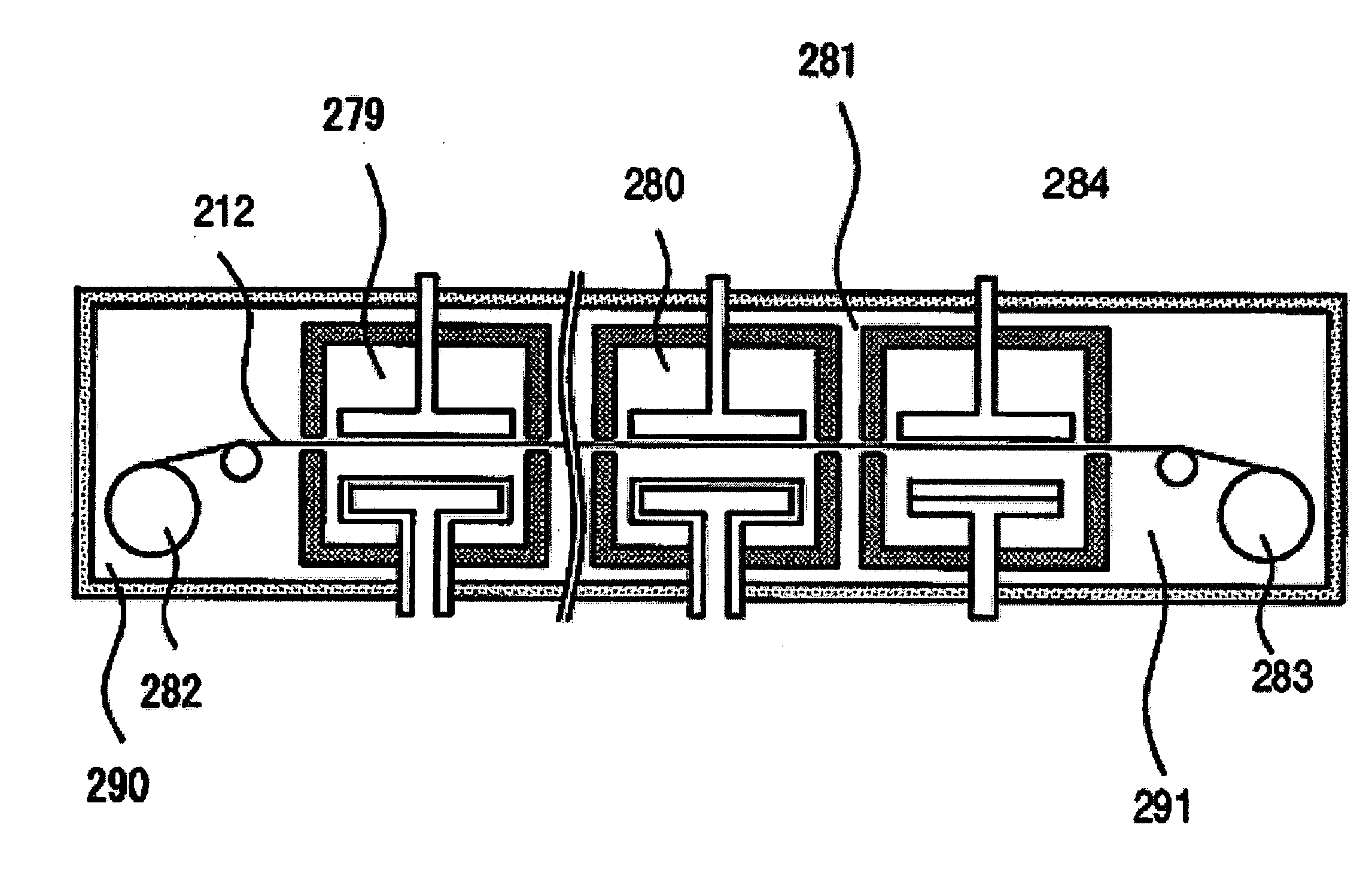
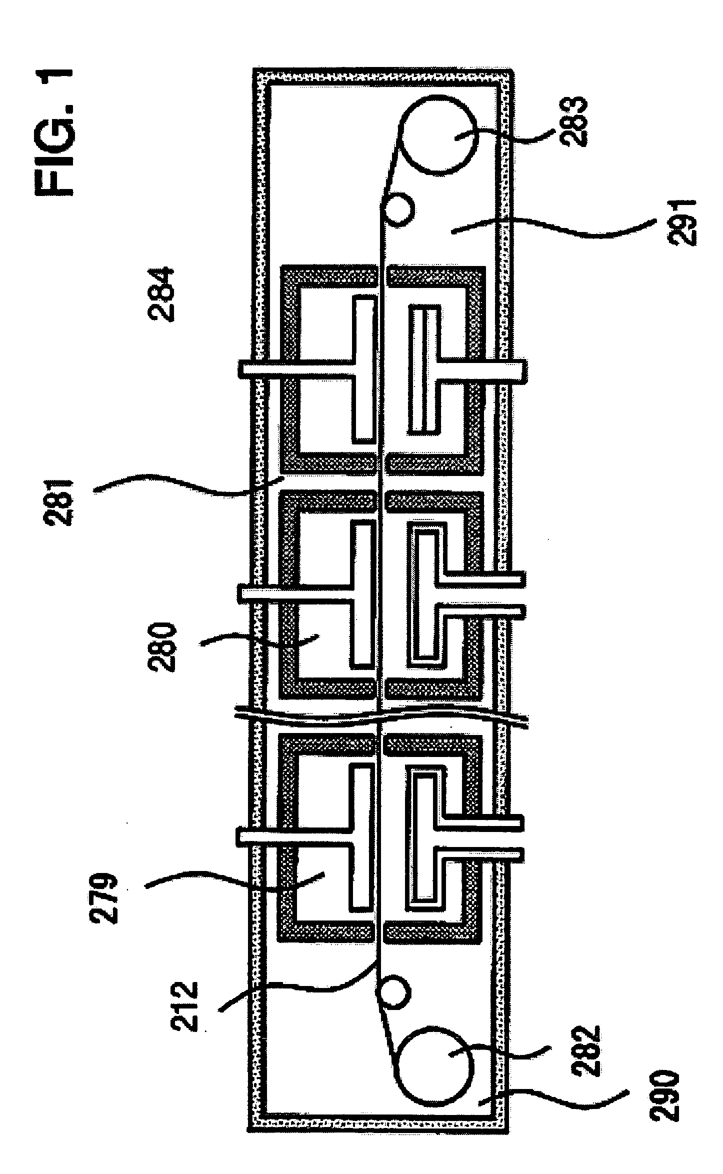
[0038] According to the plasma control method of a first embodiment of the invention, a thin film silicon solar cell is manufactured by depositing a silicon thin film such as an amorphous silicon thin film (hereinafter referred to as an “a-Si thin film”) and a micro-crystalline silicon thin film (hereinafter referred to as a “μc-Si thin film”) in a PECVD apparatus. The electrode is 1 m×1 m in area. A power supply (high-frequency electric power supply), the frequency of which is set at 13 MHz or 27 MHz, is connected to a high-frequency-wave electrode (first electrode), and an earth electrode (second electrode) is grounded. The high-frequency electric power supply is connected to the high-frequency-wave electrode at multiple power supply points intentionally positioned thereon to obtain a uniform potential distribution or to obtain a uniform plasma distribution over the high-frequency-wave electrode. Although the electrodes are shaped with a plate, a ladder-shaped electrode may be use...

second embodiment

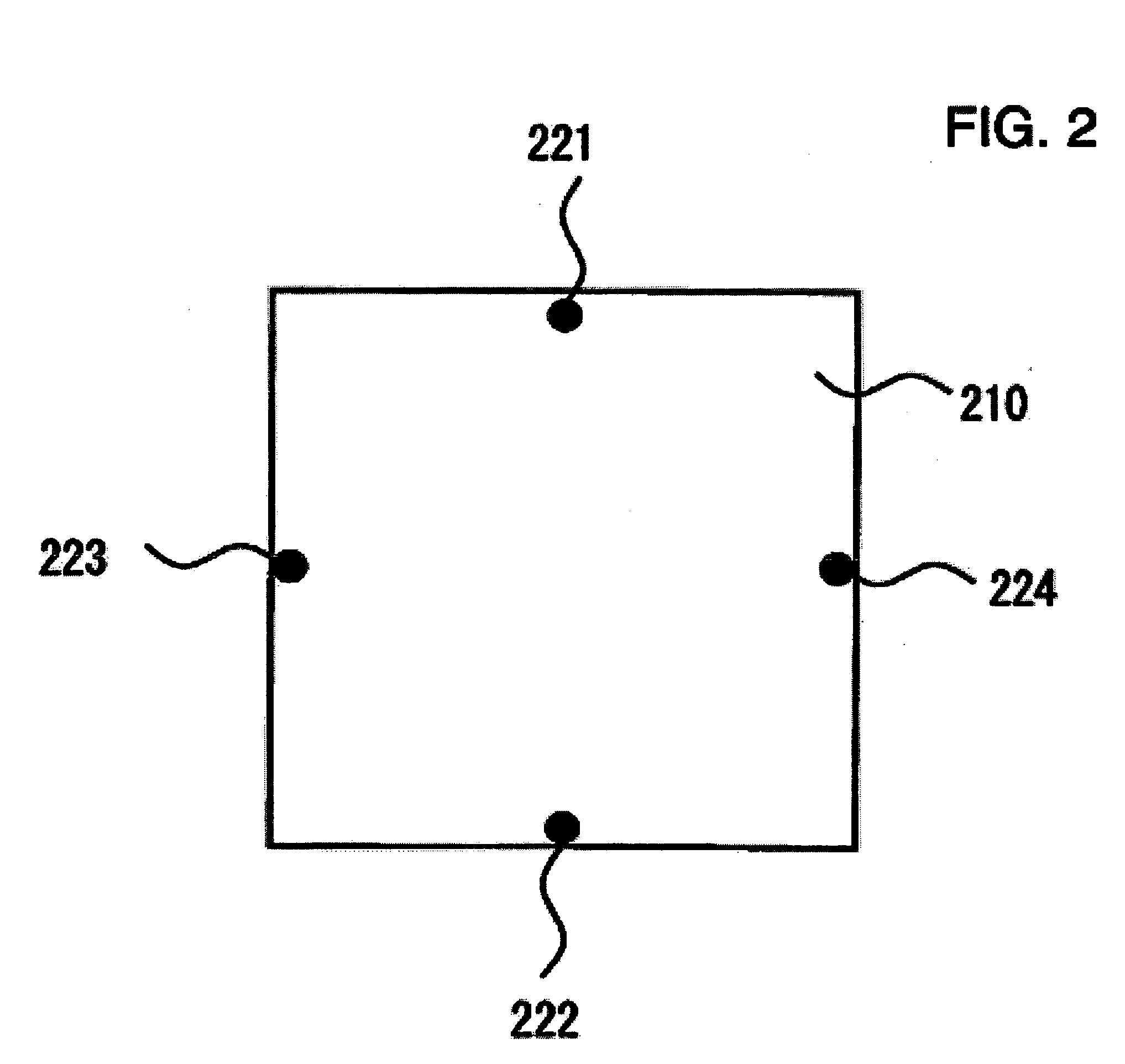
[0054] According to the second embodiment of the invention, a PECVD apparatus that facilitates the deposition of films by the stepping roll scheme in the same manner as according to the first embodiment is used. According to the second embodiment, the PECVD apparatus includes a control mechanism (automatic control means) that automatically controls, based on the peak-to-peak voltages Vpp measured at the respective measuring points, the film deposition pressure such that the differences between the absolute values of the peak-to-peak voltages Vpp are minimized (such that the peak-to-peak voltages Vpp are nearly the same). In detail, since the peak-to-peak voltage Vpp measured at the lower measuring point is much different from the peak-to-peak voltages Vpp measured at the other measuring points as described in connection with the first embodiment, the film deposition pressure is controlled so that the difference between the peak-to-peak voltage Vpp at the upper measuring point and th...


PUM


Abstract

A method that controls the distribution of a plasma generated in a vacuum chamber, for example as part of a plasma thin film deposition or plasma etching process. For thin film deposition, the method serves to minimize variations in film thickness caused by the variations of the film deposition conditions. The vacuum chamber includes a high-frequency-wave electrode connected to a high-frequency electric power supply and an earth electrode connected to the ground potential by high frequency-electric power fed to high-frequency-wave electrode. Peak-to-peak voltages are measured at multiple measuring points on one of the two electrodes. The distribution of the plasma is controlled by adjusting the chamber pressure to minimize the differences between the measured peak-to-peak voltages.

Description

CROSS-REFERENCE TO RELATED APPLICATION [0001] This application claims the foreign priority benefit of applicant's Japanese application serial no. JP-2004-338088, the disclosure of which is incorporated herein by reference. FIELD OF THE INVENTION [0002] The invention relates to a plasma control method for controlling the distribution of a generated plasma. Specifically, the invention relates to a plasma control method for controlling the distribution of the plasma generated by high-frequency electric power fed to a high-frequency-wave electrode in a vacuum chamber. The method is part of a process of plasma thin film deposition, wherein the high-frequency-wave electrode is connected to a high-frequency electric power supply and an earth electrode faces the high-frequency-wave electrode and is connected to the ground potential or a predetermined other electric power supply. BACKGROUND OF THE INVENTION [0003] Thin film deposition using a plasma and etching using a plasma have been emplo...

Claims


Application Information

Patent Timeline
IPC IPC(8): H01L21/31
CPCH01J37/32091H01J37/32935H01L31/0465Y02E10/50H01L31/202H01L31/206H01L31/03926Y02P70/50
Inventor SHIMOSAWA, MAKOTO
Owner FUJI ELECTRIC CO LTD
Why Eureka
Eureka Blog
Learn More