Transparent thin-film solar cell module and its manufacturing method

a technology of solar cells and manufacturing methods, applied in semiconductor/solid-state device manufacturing, electrical apparatus, semiconductor devices, etc., can solve the problems of insufficient luminance and resolution of thin-film solar cells, insufficient appearance and output of solar cells, and steep reduction of light transmittance, etc., to achieve high transmittance and weatherability, high conversion efficiency, and high reliability

Inactive Publication Date: 2006-06-01
KANEKA CORP
View PDF8 Cites 66 Cited by
  • Summary
  • Abstract
  • Description
  • Claims
  • Application Information

AI Technical Summary

Benefits of technology

[0022] The above-described transparent thin-film solar-cell module has high reliability by providing a back sealer composed of a fluorocarbon resin or glass, which has high transmittance and weatherability, on the multilayer film.
[0023] By performing reverse bias treatment after forming the light-transmissive aperture holes, the transparent thin-film solar-cell module having high conversion efficiency can be produced.

Problems solved by technology

When the aperture portions in the module are formed of aperture holes, unless the interval between adjacent aperture holes is satisfactorily small, it is visually recognized that the aperture holes are discontinuous; hence, a background or an image observed via the transparent thin-film solar-cell module has insufficient luminance and resolution and becomes blurry.
Furthermore, excessively small aperture holes result in a steep reduction in light transmittance.
Excessively large aperture holes result in a problem in the appearance and the output of the solar cell.
Therefore, there is a problem that the “reverse bias treatment” is insufficiently performed.
This limits the scanning velocity of the laser light.
An increase in the ratio of the light-transmissive aperture holes to the transparent thin-film solar-cell module results in generation of a clear image, but results in reductions in photoelectric conversion properties.

Method used


Image

  • Transparent thin-film solar cell module and its manufacturing method
  • Transparent thin-film solar cell module and its manufacturing method
  • Transparent thin-film solar cell module and its manufacturing method

Examples


example 1

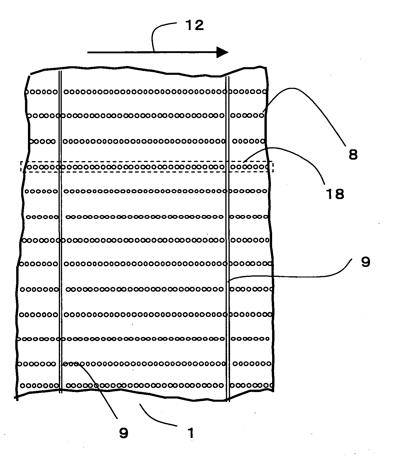
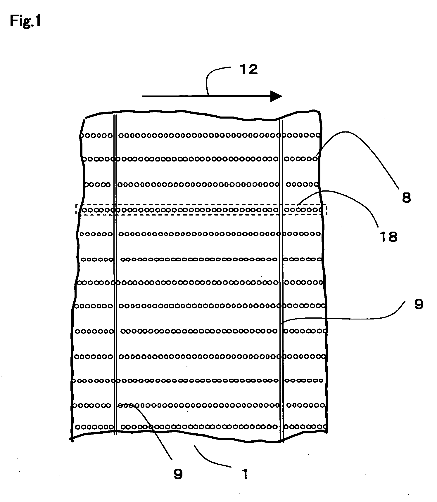
[0076] In Example 1, aperture portions 18 each including isolated light-transmissive aperture holes 8 disposed in a straight line were formed by irradiating an integrated thin-film solar cell 11 with laser light incident on the glass substrate 2 side under the following conditions: Q-switching frequency, 1 kHz; power at processing point, 0.30 W; and scanning velocity, 200 mm / s.

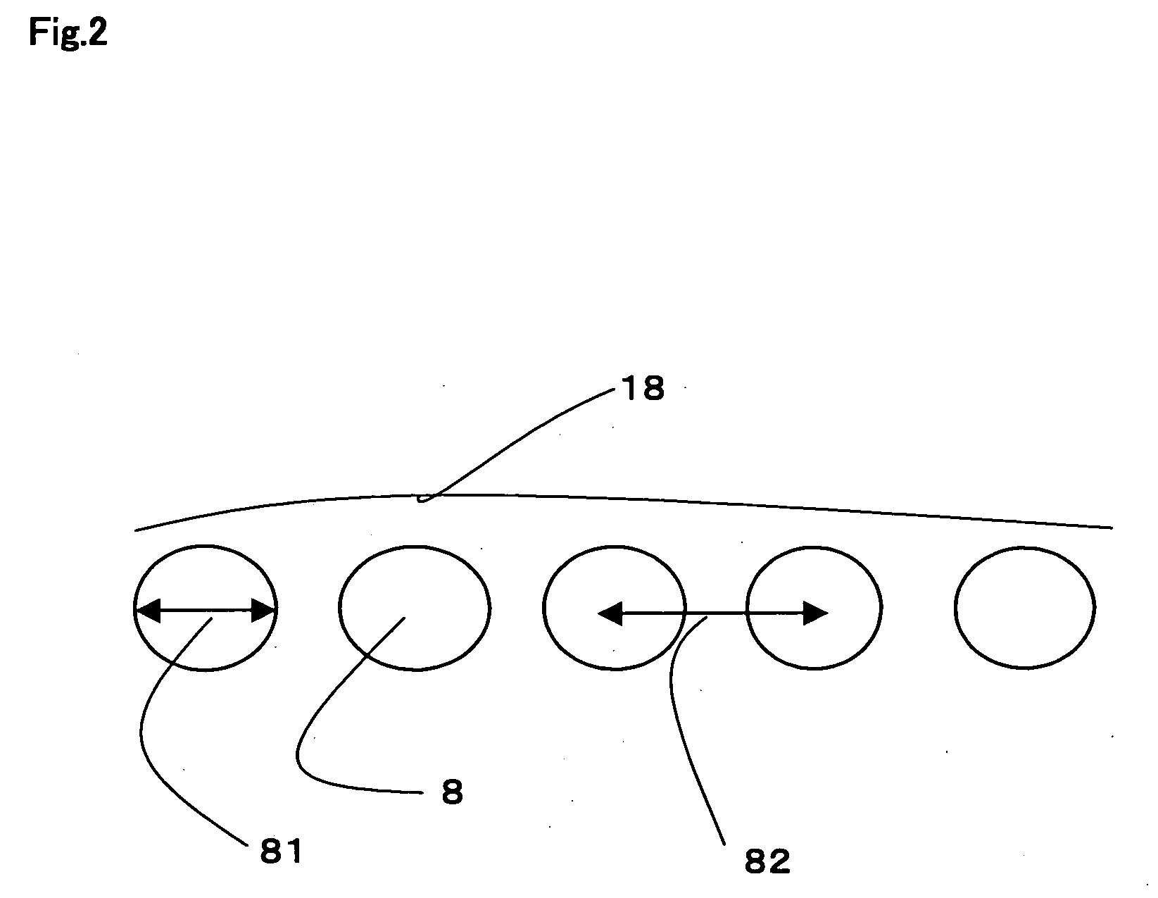
[0077] The average diameter 81 of the resulting light-transmissive aperture holes 8 was 170 μm. The distance 82 between the centers of the light-transmissive aperture holes 8 was 200 μm. The average length of non-processed opaque portions between the light-transmissive aperture holes 8 was 30 μm. Consequently, a transparent thin-film solar-cell module 1 having an aperture ratio of 11.3% was obtained. With respect to the photoelectric conversion properties, the open-circuit voltage was 88.8 V, the short-circuit current was 1.008 A, the fill factor was 0.609, and the maximum output was 54.5 W.

[0078] An image w...

example 2

[0079] In Example 2, aperture portions 18 each including isolated light-transmissive aperture holes 8 disposed in a straight line were formed by irradiating an integrated thin-film solar cell 11 with laser light incident on the glass substrate 2 side under the following conditions: Q-switching frequency, 1 kHz; power at processing point, 0.30 W; and scanning velocity, 300 mm / s.

[0080] The average diameter 81 of the resulting light-transmissive aperture holes 8 was 170 μm. The distance 82 between the centers of the light-transmissive aperture holes 8 was 300 μm. The average length of non-processed opaque portions between the light-transmissive aperture holes 8 was 130 μm. Consequently, a transparent thin-film solar-cell module 1 having an aperture ratio of 7.5% was obtained. With respect to the photoelectric conversion properties, the open-circuit voltage was 89.8 V, the short-circuit current was 1.050 A, the fill factor was 0.612, and the maximum output was 57.7 W.

[0081] An image w...

example 3

[0082] In Example 3, aperture portions 18 each including isolated light-transmissive aperture holes 8 disposed in a straight line were formed by irradiating an integrated thin-film solar cell 11 with laser light incident on the glass substrate 2 side under the following conditions: Q-switching frequency, 1 kHz; power at processing point, 0.10 W; and scanning velocity, 100 mm / s.

[0083] The average diameter 81 of the resulting light-transmissive aperture holes 8 was 80 μm. The distance 82 between the centers of the light-transmissive aperture holes 8 was 100 μm. The average length of non-processed opaque portions between the light-transmissive aperture holes 8 was 20 μm. Consequently, a transparent thin-film solar-cell module 1 having an aperture ratio of 5.0% was obtained. With respect to the photoelectric conversion properties, the open-circuit voltage was 89.5 V, the short-circuit current was 1.062 A, the fill factor was 0.623, and the maximum output was 59.2 W.

[0084] An image was...


PUM


Abstract

A transparent thin-film solar-cell module having high output, high light transmittance, and excellent appearance, the module including a plurality of photoelectric conversion cells connected in series, the cells containing a first electrode layer, a semiconductor layer, and a second electrode layer stacked in that order on a main surface of a transparent insulating substrate; and a plurality of light-transmissive aperture holes formed by removing at least the second electrode layer, the light-transmissive aperture holes each having a diameter of 30 μm to 500 μm, the plurality of light-transmissive aperture holes being disposed in a line at a distance between the centers of the light-transmissive aperture holes of 1.01 to 2 times the diameter of each light-transmissive aperture hole, and a method for producing the module.

Description

TECHNICAL FIELD [0001] The present invention relates to a thin-film solar-cell module. In particular, the present invention relates to a transparent thin-film solar-cell module having light transmittance and being usable as a light-transmitting screen, a background being viewable through the module. BACKGROUND ART [0002] In general, a typical thin-film solar cell often has the structure of an integrated thin-film solar cell 11 shown in FIG. 3. In FIG. 3, a photoelectric conversion cell 10 includes a first electrode layer 3, a semiconductor layer 4, and a second electrode layer 5 stacked in that order on a transparent insulating substrate 2. That is, in the integrated thin-film solar cell 11, light incident on the transparent insulating substrate 2 or the second electrode layer 5 is subjected to photoelectric conversion by a photoelectric conversion unit in the semiconductor layer 4. [0003] The integrated thin-film solar cell 11 shown in FIG. 3 includes first isolation grooves 21, se...

Claims


Application Information

Patent Timeline
Patent Type & Authority Applications(United States)
IPC IPC(8): H01L31/00H01L31/042
CPCH01L31/03921H01L31/0468Y02E10/50H01L31/0445H01L31/18
Inventor NAKATA, TOSHINOBUYAMAGISHI, HIDEO
Owner KANEKA CORP
Why Eureka
Try Eureka