
Information recording apparatus and information recording method

Inactive Publication Date: 2006-06-01
SONY CORP
View PDF0 Cites 18 Cited by
  • Summary
  • Abstract
  • Description
  • Claims
  • Application Information

AI Technical Summary

Benefits of technology

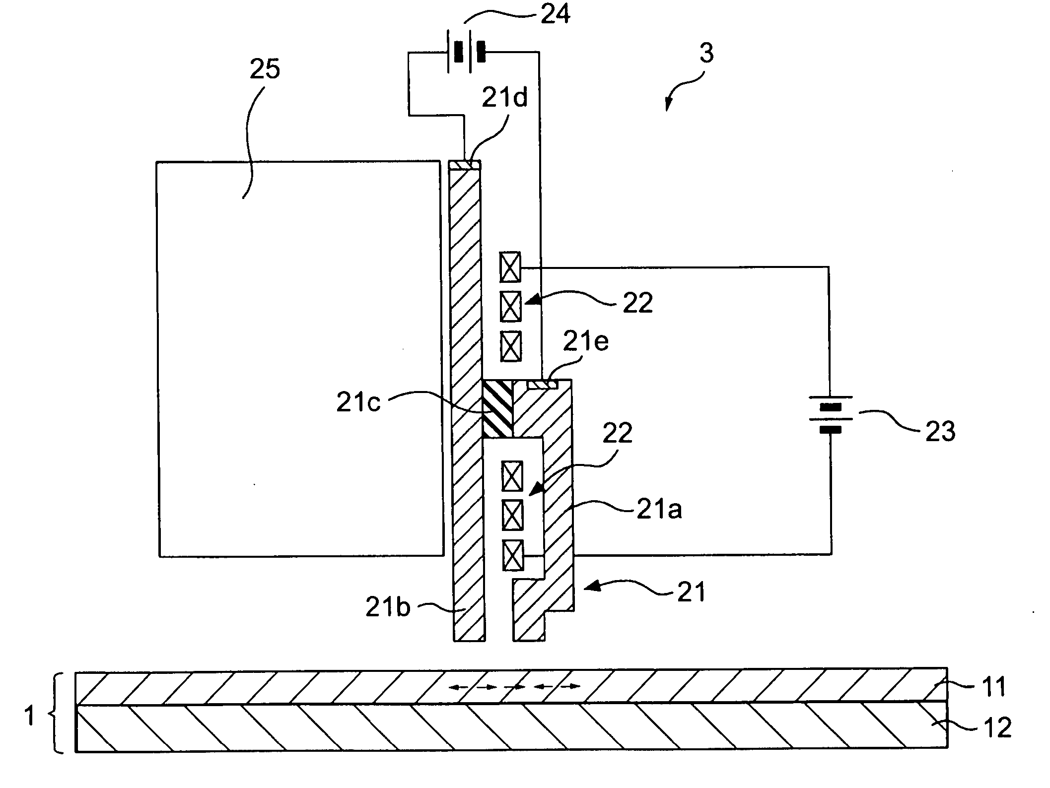
[0034] According to the above embodiments of the present invention, the electric field is generated in the magnetic recording layer of the recording medium, so that the coercive force of the recording layer is decreased. Hence, magnetization can be recorded by a lower magnetic field than an intrinsic coercive force of the magnetic recording layer.
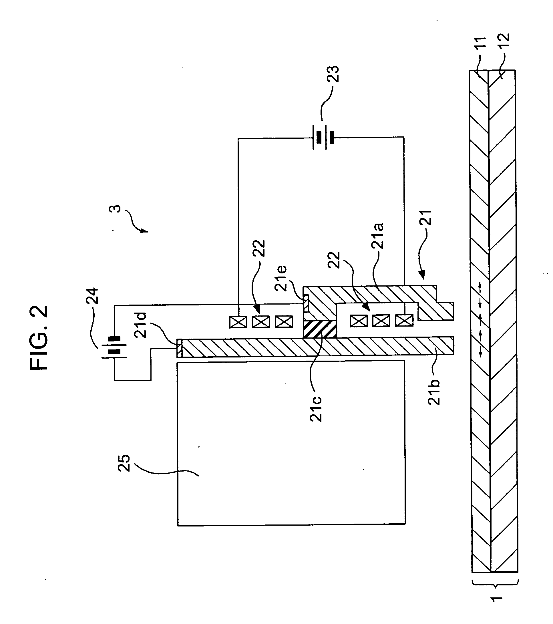
[0035] According to the embodiments of the present invention, when magnetization is recorded on the magnetic recording layer of the recording medium by the recording head, the electric field is generated in the magnetic recording layer, thereby decreasing the coercive force thereof. Hence, the magnetization can be recorded at a magnetic field lower than the intrinsic coercive force of the magnetic recording layer. Consequently, even when a recording medium having a high coercive force is used for high density recording, without using a recording head generating a significantly high magnetic field, high density magnetic recording can be effectively realized.
[0036] Furthermore, in order to generate the electric field, the structure in which the voltage source is connected to the magnetic pole layers (or the magnetic pole layer and the conductive layer of the recording medium) may only be formed; hence, for example, unlike the case of heat assisted recording using laser light, it is not necessary to provide the optical pickup mechanism, to perform considerable change in structure of the magnetic head, and to perform the control thereof. As a result, the magnetic recording apparatus according to the embodiment of the present invention can be easily realized, and hence a highly practical magnetic recording apparatus can be effectively provided. For example, the magnetic recording apparatus described above can be easily used as a hard disc drive.

Problems solved by technology

However, it has been known that the intensity of a magnetic field generated by a currently available recording head used for magnetic recording has a limitation.
Accordingly, as long as currently available recording heads are used, the intensity of the magnetic field generated thereby may not be able to exceed the coercive force in the future.

Method used


Image

  • Information recording apparatus and information recording method
  • Information recording apparatus and information recording method
  • Information recording apparatus and information recording method

Examples


Embodiment Construction

[0045] Hereinafter, with reference to a hard disc drive as an example, embodiments of the present invention will be described in the following order.

[0046] 1. Magnetic Recording with Electric Field Application

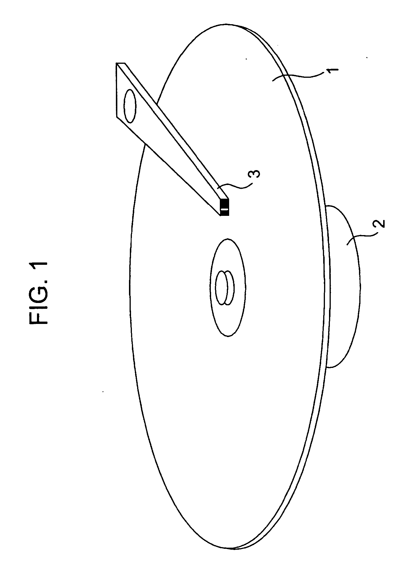
[0047] 2. Structure of a Hard Disc Device

[0048] 3. Example Using a Longitudinal Magnetic Recording Head

[0049] 4. Example Using a Perpendicular Magnetic Recording Head

[0050] 1. Magnetic Recording with Electric Field Application

[0051] In this embodiment, in order to perform magnetic recording by a magnetic field lower than the coercive force of a recording medium (magnetic disc), in magnetic recording, the coercive force is decreased by applying an electric field to the recording medium.

[0052] As described above, although there have been still various problems when magnetic recording is performed at a magnetic field lower than the coercive force using a heat assisted recording method, the above problems can be solved by an electric field application method. Hereinafter, th...


PUM


Abstract

Magnetic recording is performed by a magnetic field lower than a coercive force without considerably changing the structure of a magnetic head and the vicinity thereof. When recording is performed by applying a magnetic field to a magnetic recording layer of a recording medium using a magnetic head, the electric field is generated in the magnetic recording layer so that the coercive force thereof is decreased. Accordingly, magnetization is recorded by a lower magnetic field than an intrinsic coercive force of the magnetic recording layer. In order to generate the electric field, a power source is connected to magnetic pole layers of a longitudinal magnetic recording head (or to a magnet pole layer of a perpendicular magnetic recording head and a conductive layer of a recording medium thereof).

Description

CROSS REFERENCES TO RELATED APPLICATIONS [0001] The present invention contains subject matter related to Japanese Patent Application JP 2004-328394 filed in the Japanese Patent Office on Nov. 12, 2004, the entire contents of which are incorporated herein by reference. BACKGROUND OF THE INVENTION [0002] 1. Field of the Invention [0003] The present invention relates to an information recording apparatus using a recording head, such as a magnetic head, which performs magnetic field modulation, and to an information recording method. [0004] 2. Description of the Related Art [0005] In information recording methods using a magnetic tape, a magnetic disc, and the like, a magnetic field is generated in a particular area of a magnetic recording film by using a magnetic recording head which generates magnetic fields having different directions depending on information, so that the information is recorded by changing the direction of the magnetization in the above particular area. [0006] In th...

Claims


Application Information

Patent Timeline
IPC IPC(8): G11B5/127
CPCB82Y10/00G11B5/1278G11B5/65G11B5/66G11B9/149G11B2005/001G11B5/658G11B5/676G11B5/657G11B5/672
Inventor IDE, NAOKI
Owner SONY CORP
Learn More