Pathological diagnosis support device, program, method, and system

a technology of pathological diagnosis and support device, applied in the field of pathological diagnosis support device, can solve the problems of long time consumed to produce high reliability, parts of the image indicating the feature cannot be detected with high precision, and the properties of foreign substances cannot be identified, etc., to achieve the effect of short time and high accuracy

Active Publication Date: 2006-06-01
NEC CORP
View PDF7 Cites 30 Cited by
  • Summary
  • Abstract
  • Description
  • Claims
  • Application Information

AI Technical Summary

Benefits of technology

[0061] In accordance with the present invention, in consideration of importance of changes taking place in a cell nucleus, peripheral tissues thereof, and the like in the discrimination of properties of a tumor, subimages primarily including cell nuclei, pores, cytoplasm, and ...

Problems solved by technology

However, since the devices produce only positional information of foreign substances, properties of the foreign substances cannot be identified.
However, the above inventions are attended with problems as follows.
However, since the operation requires a considerably large volume of learning data, a long period o...

Method used


Image

  • Pathological diagnosis support device, program, method, and system
  • Pathological diagnosis support device, program, method, and system
  • Pathological diagnosis support device, program, method, and system

Examples


second embodiment

[0166] Next, description will be given of a second embodiment in which effective noise is added to learning patterns in accordance with the present invention.

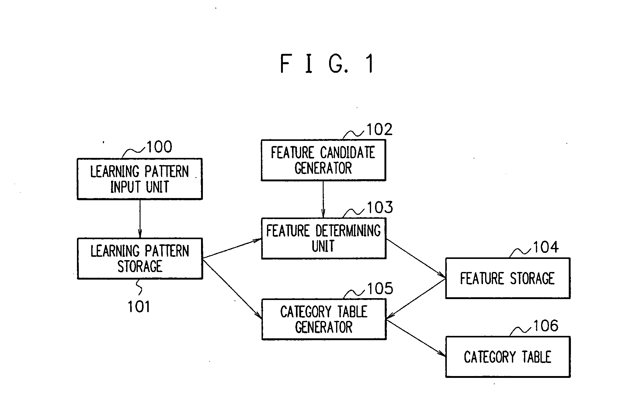
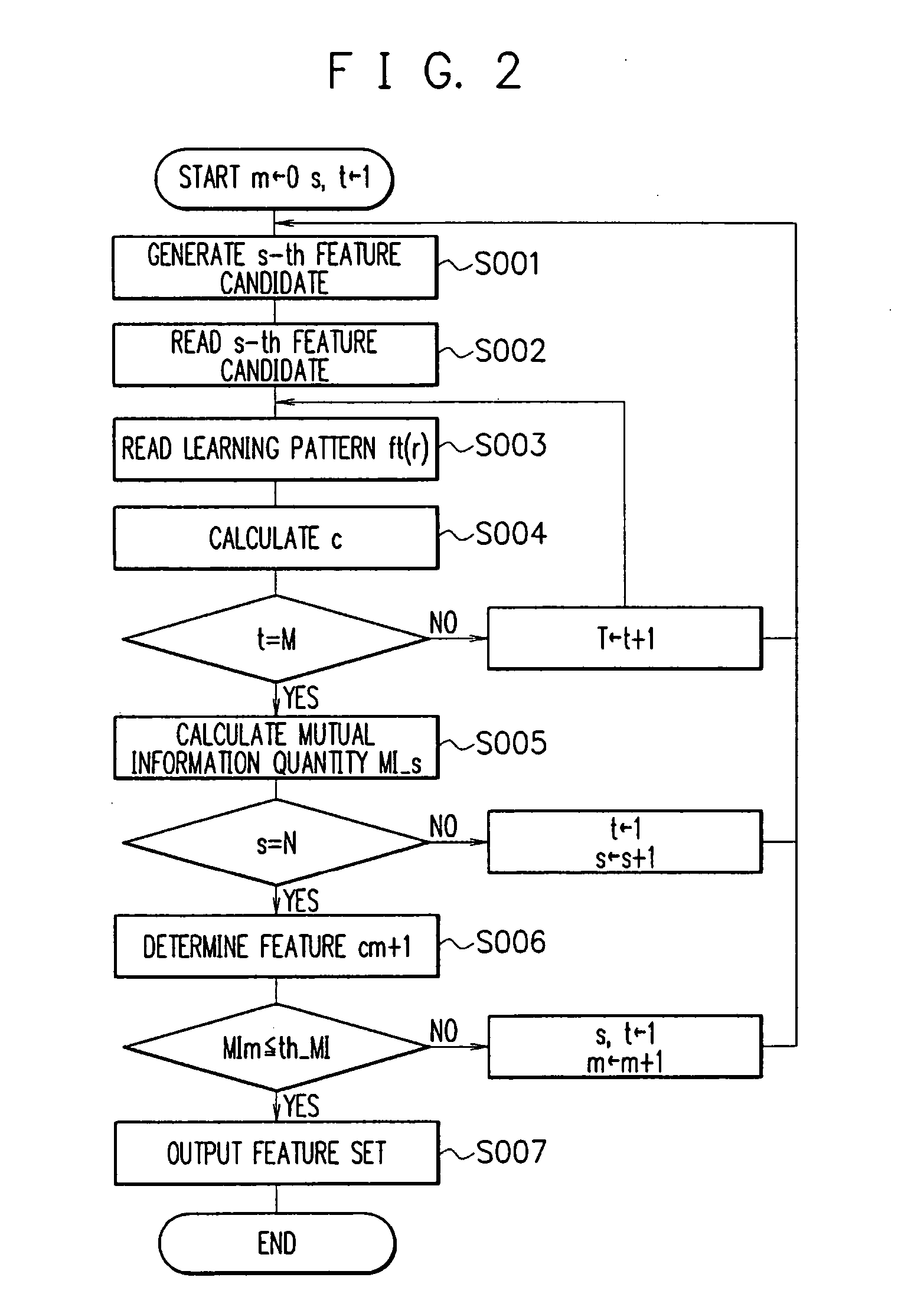
[0167] The system configuration of the second embodiment is almost the same as that of the first embodiment (reference is to be made to FIG. 1). The processing flow of the second embodiment is substantially equal to that of the first embodiment (reference is to be made to FIGS. 2 to 6). Description will be given of only the difference between the first and second embodiments.

[0168] According to procedure 1 of the embodiment, there has been prepared a noise parameter (s≦N—1) in the feature parameter set in addition to (k_s, r0_s, σ_s, th_s) for the feature candidate generator 102. As in step S001 of the first embodiment, the generator 102 substitutes an s-th feature parameter set (k_s, r0_s, σ_s, th_s, σn_s) for (k, r0, σ, th), where the initial value of s is one, to thereby generate the complex Gabor function and the Gaussian...

third embodiment

[0196] Description will now be given of a third embodiment in accordance with the present invention by referring to the drawings. Also in this embodiment, the operation can be extended to handle three classes or more as in the first and second embodiments. However, in the description of the third embodiment, operation is conducted with two classes (q=0 or 1) for convenience of description.

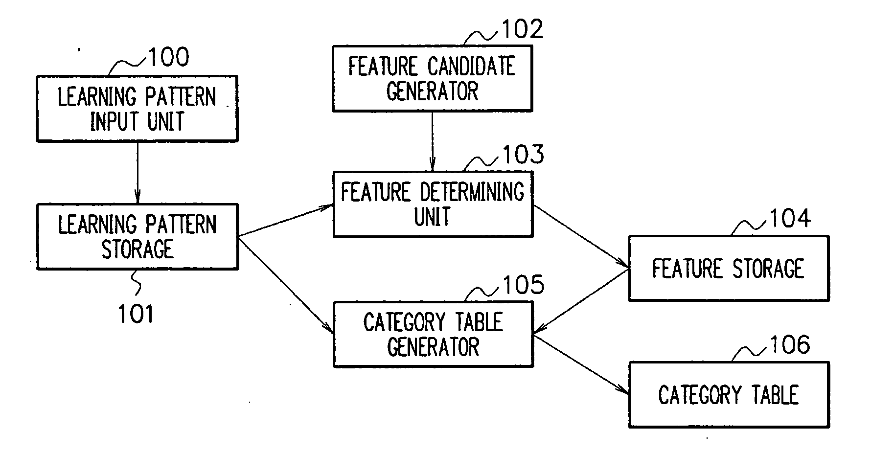
[0197]FIG. 8 shows in a block diagram a system configuration of the third embodiment of the feature selection method in accordance with the present invention. The system of FIG. 8 includes a learning pattern input unit 300, a learning pattern storage 301, a feature candidate generator 302, a feature determining unit 303, a feature storage 304, and a transition table 305. Description of the same constituent components as those of the first and second embodiments will be avoided.

[0198] The feature determining unit 303 is a module to determine, using the feature candidates created by the feature can...

fourth embodiment

[0241] Description will now be given of a configuration and operation of a pathological diagnosis support system including a pathological diagnosis support device associated with the first to third embodiments.

[0242] Description will be given of a configuration of the pathological diagnosis support system according to the fourth embodiment.

[0243] The system includes a microscope 1601, a pathological image processing terminal 160, a pathological diagnosis support server 1603, and an accounting server 1604. The terminal 160 and the servers 1603 and 1604 are connected via a network to each other. The pathological diagnosis support server 1603 includes a pathological diagnosis support device 1603a and a diagnosis result storage 1603b associated with the first to third embodiments.

[0244] The microscope 1601 and the pathological image processing terminal 160 are installed in a medical institution such as a hospital. The microscope 1601 is a device to shoot a focus of a patient to produ...


PUM


Abstract

A pathological diagnosis support device, a pathological diagnosis support program, a pathological diagnosis support method, and a pathological diagnosis support system extract a pathological tissue for diagnosis from a pathological image and diagnose the pathological tissue. A tissue collected in a pathological inspection is stained using, for example, hematoxylin and eosin. In consideration of the state of the tissue in which a cell nucleus and its peripheral constituent items are stained in respective colors unique thereto, subimages such as a cell nucleus, a pore, cytoplasm, interstitium are extracted from the pathological image, and color information of the cell nucleus is also extracted. The subimages and the color information are stored as feature candidates so that presence or absence of a tumor and benignity or malignity of the tumor are determined.

Description

BACKGROUND OF THE INVENTION [0001] 1. Field of the Invention [0002] The present invention relates to a pathological diagnosis support device, and in particular, to a pathological diagnosis support device, pathological diagnosis support program, pathological diagnosis support method, and pathological diagnosis support system in which a pathological tissue to be diagnosed is extracted from a pathological image for diagnosis thereof. [0003] 2. Description of the Prior Art [0004] In a clinical site, subtle extraordinary events can be detected thanks to development of diagnosis support devices using images such as images produced by x-ray photography, computer tomography (CT), and magnetic resonance imaging (MRI). However, since the devices produce only positional information of foreign substances, properties of the foreign substances cannot be identified. In consequence, a pathological expert observes by a microscope the foreign substances detected by the diagnosis device and determines...

Claims


Application Information

Patent Timeline
IPC IPC(8): G06K9/62G06K9/00A61B5/00G01N33/48G06T1/00G06T7/00G06V10/771
CPCG06F19/363G06K9/00127G06K9/6228G16H10/20G06V20/69G06V10/771G06F18/211
Inventor OGURA, MAKISAITOU, AKIRAKAMIJO, KENICHIOKAJIMA, KENJIKIYUNA, TOMOHARU
Owner NEC CORP
Why Eureka
Try Eureka