Mini eye drop tip

Inactive Publication Date: 2006-06-01
ACU I DROP
View PDF32 Cites 17 Cited by
  • Summary
  • Abstract
  • Description
  • Claims
  • Application Information

AI Technical Summary

Benefits of technology

[0015] The present invention is an improved tip for droppers, such as for eye drops, to dispense and instill medicinal liquids into a patient's eye. The dropper creates a much smaller drop of liquid than conventional dropper tips and is thus beneficial in treating such conditions as the dry eye. It is designed so that the droplet falls from the distal free end of the tip rather than adhering and traveling along the outer surface of the stem of the tip even when held in a near horizontal orientation over the eye. The tip has a unique shape and is made of a soft, supple material. The tip of the present invention is integrated with a reservoir of medicinal liquid. The reservoir is squeezed to dispense medicinal liquid out the small opening in the distal free end of the tip. The diameter of the external opening of the tip is extremely small and the walls of the external opening of the tip are very narrow. This combination provides for the creation of a small droplet that consistently falls from the distal free end of the tip rather than adhering to the external surface of the tip. The present invention dropper tip fits into any conventional eye dropper bottle.
[0016] This invention permits the bottle to be held either at a near vertical position or a near horizontal orientation and still give more accuracy in delivering the drop to the intended target. The present invention provides for creating a small droplet to instill into the eye and permits the dropper bottle to be held either vertically or horizontally over the eye.
[0017] Eye dropper tips are not to touch the eye during normal use because of possible harm to ocular structures and also risk of contamination. However, unintentional contact can occur. The distal end of the dropper tip of the present invention is made of a soft and supple material, thus reducing the harm that might come from an accidental touching of the eye. The external opening of the tip is extremely small in diameter and the walls of the opening of the tip are very narrow, thus providing little area for a drop to be held to the tip by surface tension. This provides for the falling of the drop from the free end of the dropper tip as a small droplet. OBJECTS OF THE INVENTION

Problems solved by technology

The placement of medicinal liquid into a patient's eye tends not only to be difficult but wasteful.
This not only creates a waste of drops, but can be irritating to the skin and eye.
Many individuals do not make an adequate amount of tears and thus the eye may have symptoms of burning, irritation or sandy feeling, itching, and even a decrease in visual acuity since the tear film is responsible for maintaining good vision.
This sudden excess of moisture that is instilled into the eye at one time may be more harmful than beneficial if it irrigates away the mucin, lipid layers and proteins of the tear film.
Also, when an excess of medicinal drop is used, the patient wipes the eye profusely with tissue or cloth and thereby risks the removal of the beneficial lipids that are produced by the oil glands of the eyelids.
If artificial tears are instilled into an eye too frequently, there is the fear of washing out the more beneficial components of the tear film, such as the mucin layer, the lipid layer and other elements.
The repeated use of tissues for removing the excess medication from the eye and eyelids may be dehydrating and counter productive to the treatment of the dry eye.
Contact lens wearers often have symptoms of dryness of the eyes, especially when the lenses are worn for longer periods of time or in certain situations where dehydration of the eye occurs.
When a large drop or drops are instilled into an eye with a patient wearing contact lenses, there is a tendency for this large volume to “float” the lens and can cause it to slide off the cornea where it must remain for good visual acuity.
One example is that certain anti-glaucoma medications have the side effect of causing eyelashes to grow and thicken.
Although a patient may have the end of the prior tip located directly above the eye, the drop will likely roll down the tip to release at a point away from the end of the tip and miss the eye altogether.

Method used


Image

  • Mini eye drop tip
  • Mini eye drop tip
  • Mini eye drop tip

Examples


Embodiment Construction

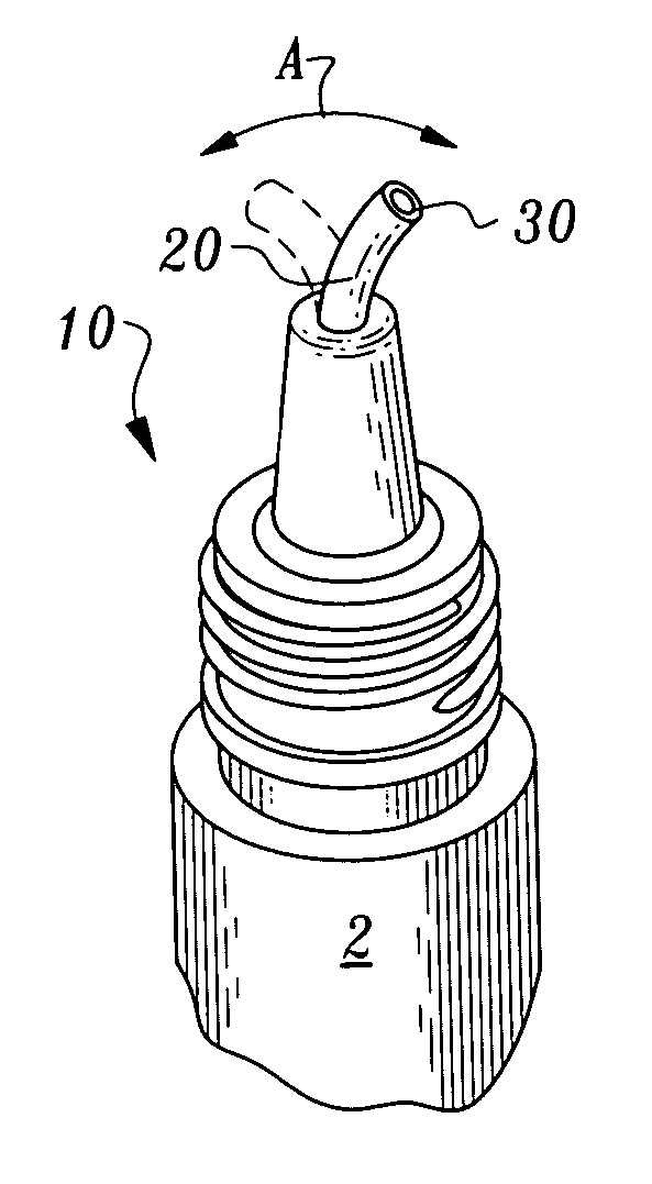
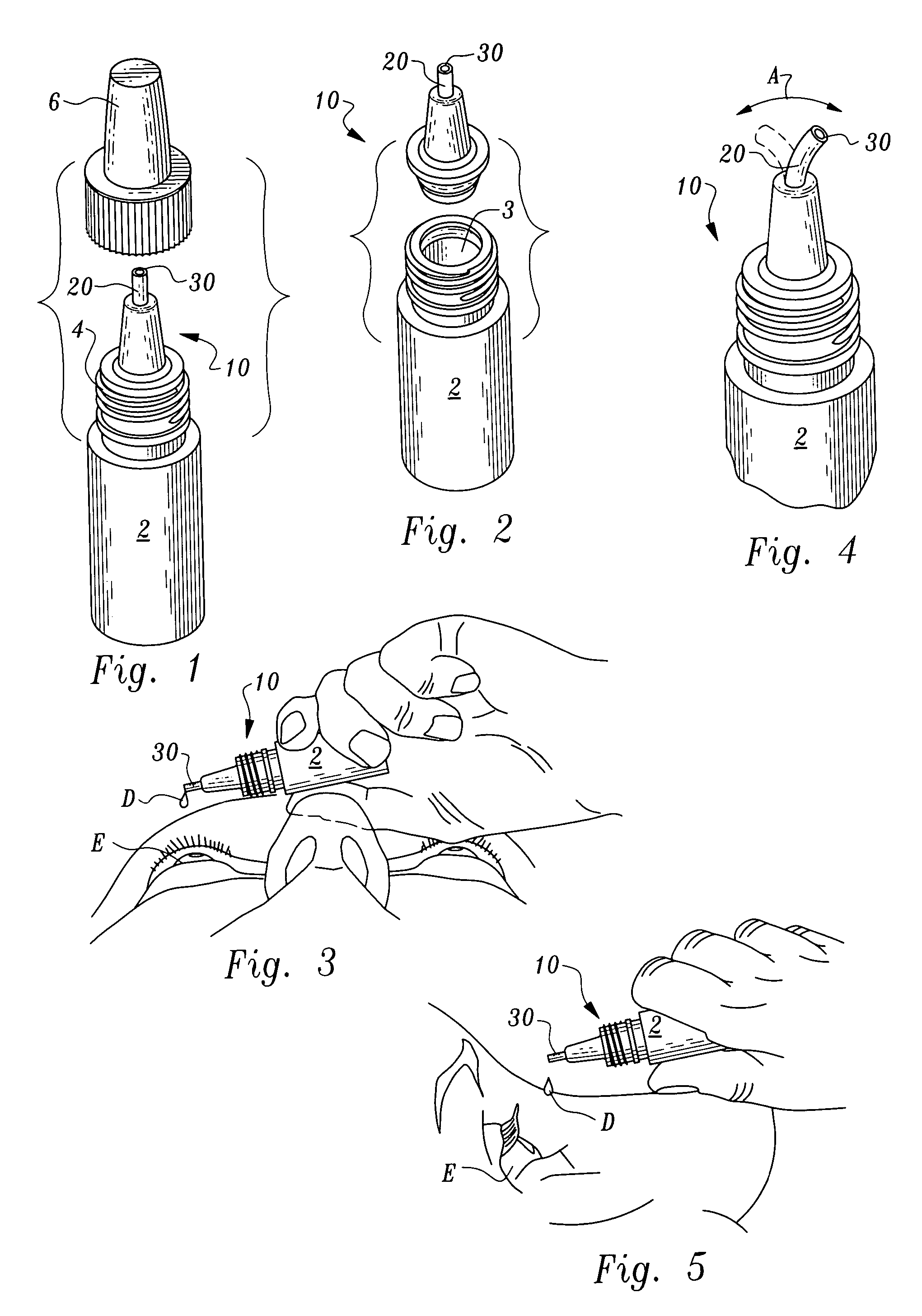
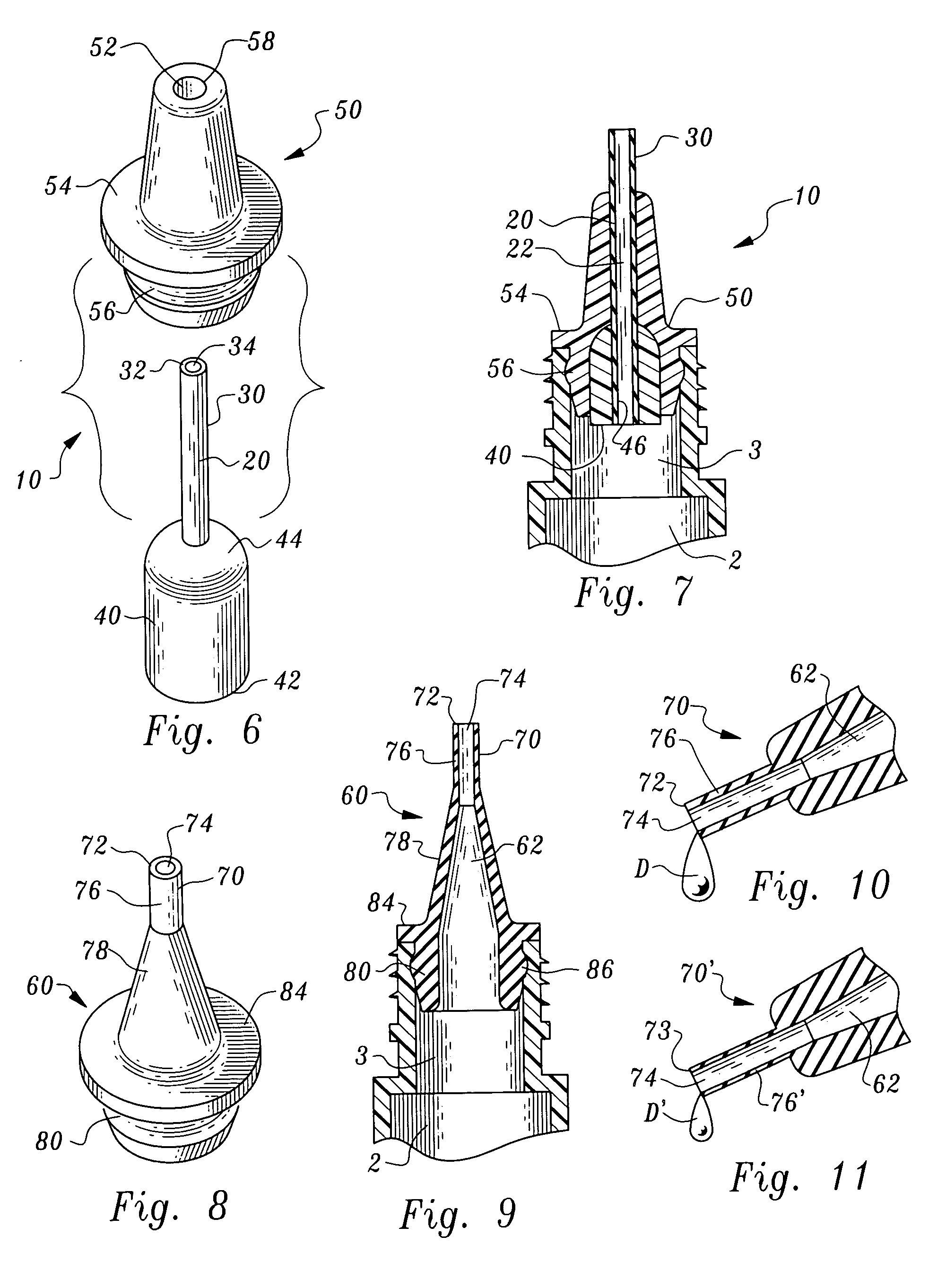
[0043] Referring to the drawings, wherein like reference numerals represent like parts throughout the various drawing figures, three illustrative embodiments of this invention are particularly described. These embodiments are described in detail to illustrate the invention as expressed in particular embodiments. However, these embodiments are not provided to limit the scope of this invention. A dispenser 10 (FIGS. 1-7) is provided according to a first embodiment. This dispenser 10 is attachable to a bottle 2, such as an eye drop containing dropper bottle so that the dispenser 10 provides an outlet for eye drops from the bottle 2. The dispenser 10 particularly provides for safe and precise release of mini drops from the dispenser, mini drops being any drops smaller than a standard drop.

[0044] In essence, and with particular reference to FIGS. 1-7, basic details of the dispenser 10 of the first embodiment are described. The dispenser 10 provides a conduit 20 extending from a source o...


PUM


Abstract

A tip is provided for a liquid dropper which facilitates formation of a mini drop, a mini drop being a drop smaller than a standard typical drop. A conduit is provided extending from a reservoir of liquid to a tip. The tip provides a location for release of the mini drop. The tip includes a rim surrounding a port with the rim having a particularly thin wall and with the port being particularly narrow. The dimensions of the rim and port facilitate formation of the mini drop. The material forming the tip is flexible and resilient so that should the tip come into contact with sensitive structures, such as an eye of a patient, a potential for injury is minimized. Dispensers featuring the unique tip are disclosed in multiple different embodiments for attachment to a bottle of liquid to be dispensed, or to fit over an existing outlet.

Description

FIELD OF THE INVENTION [0001] This invention relates to eye dropper tips for the dispensing of medicinal liquids into the eye. More particularly, this invention relates to eye dropper tips that create much smaller drops than current conventional eye dropper tips. BACKGROUND OF THE INVENTION [0002] The placement of medicinal liquid into a patient's eye tends not only to be difficult but wasteful. The eye dropper bottles and tips on the market today produce a large drop and often more than one drop spontaneously falls from the dropper bottle either into the eye or onto the skin of the face and eyelids. This not only creates a waste of drops, but can be irritating to the skin and eye. [0003] This invention creates a small droplet that falls from the free end of the tip rather than migrating along the outer surface of the stem of the dropper. The accumulation of liquid along the outer stem surface of a conventional dropper tip, when held in a near horizontal orientation, will tend to pr...

Claims


Application Information

Patent Timeline
IPC IPC(8): A61M35/00
CPCA61F9/0008
Inventor HAGELE, JAMES
Owner ACU I DROP
Why Eureka
Try Eureka