
Method and system for improved eye protection safety of distributed Raman amplifiers

a distributed raman and amplifier technology, applied in the field of optical fiber amplifiers, can solve problems such as human eye harm, pump energy escape, and potential safety hazards for persons coming into contact with the system

Inactive Publication Date: 2006-06-08
RED C OPTICAL NETWORKING +1
View PDF16 Cites 14 Cited by
  • Summary
  • Abstract
  • Description
  • Claims
  • Application Information

AI Technical Summary

Benefits of technology

[0017] The present invention discloses a system and method for providing eye-safety protection during operation of distributed Raman amplifiers based on the application of continuous out-of-band ASS monitoring, and real-time detection and analysis of changes in the monitored ASS power level. The system and method disclosed herein can detect an open span in real-time as well as provide diagnostic information with respect to the position of the opening. The system and method can also be used to assist in identifying span degradation, which could potentially develop into an open span, thus allowing preemptive corrective action to be taken.
[0026] In a preferred embodiment of the method of the present invention, the method comprises the steps of continuously monitoring an out-of-band ASS power level; detecting when changes in the ASS power level signify an open span; and, responsive to the detection result, reducing the level of Raman pump energy entering the span to a safe level. Preferably, the step of reducing the level of Raman pump energy entering the span involves activation of a complete shutdown of the Raman pump unit. Preferably, the detection and reduction of pump energy are fast enough so that the time between the opening of the span and the activation of the safety mechanism is shorter than the eye-safe time. Preferably, the method further includes the step of determining, based on the magnitude of change in the ASS power level, the approximate position of the opening once an open span has occurred. Preferably, the method further includes determining when degradation in the span has occurred before the degradation develops into an open span.

Problems solved by technology

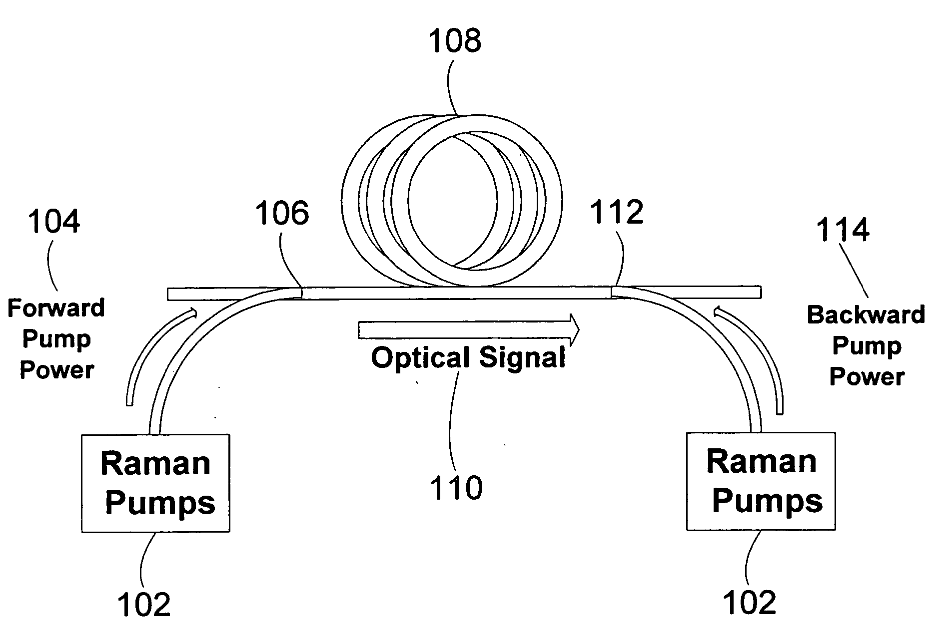
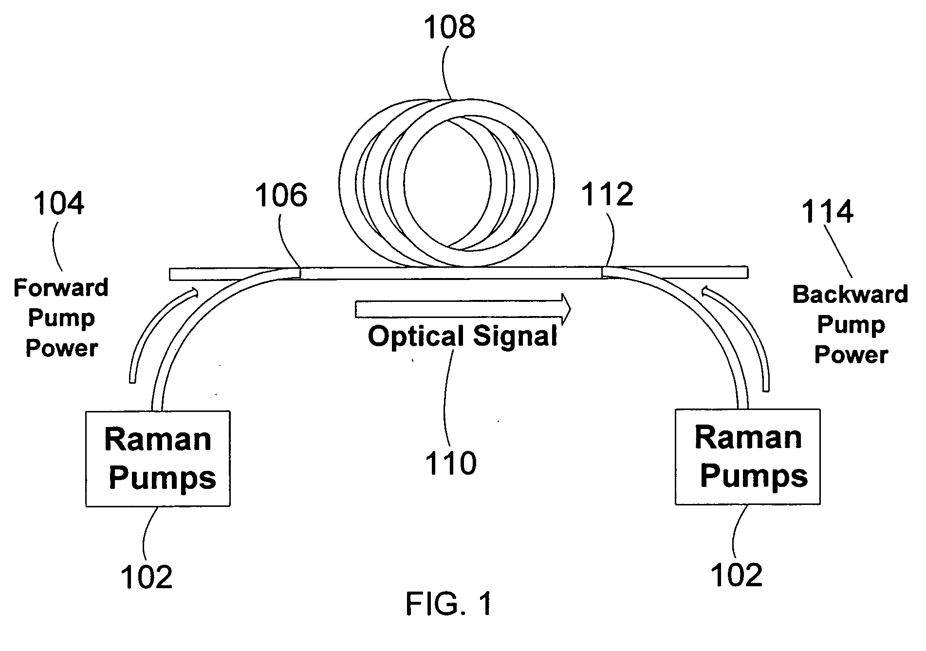
Thus, in contrast with EDFAs and other types of lumped amplifiers where the amplifier pump power remain contained within a closed unit, the high Raman pump power propagates along the transmission fiber, posing a potential safety hazard to persons coming into contact with the system.
Particularly, if the pump is operated while a connector along the span is open, or when there is a break or cut in the transmission fiber, the pump energy may escape and cause harm to human eyes, as well as material damage to the system.
As used herein, the term “open span” refers to the state where there is an open connector or fiber break or cut within the span employing the Raman amplifier, or any other situation that could cause significant leakage of pump power from the span, thus posing danger to human eyes coming in contact with the leaked power.
However, Raman amplification can complicate such monitoring due to significant levels of amplified spontaneous scattering (ASS) generated within the communication band by the pump energy (see for example J. Auyeung et al, “Spontaneous and Stimulated Raman scattering in long low loss fibers”, Journal of Quantum Electronics, Vol.
However, even if the issue of ASS in the communication band is overcome, modern communication links support Add and Drop of signal channels, which can lead to drastic changes in the signal level even if the span is still functional.
This is an inherent problem with using signal channel detection as a safety mechanism.
The disadvantage of using the supervisory channel is that it is not present in all systems, and in any case it involves relying on a feature of the system external to the Raman amplifier.
For example, opening a PC type connector within a certain distance of the Raman amplifier will cause a detectable increase in pump energy back-reflection.
A main disadvantage is that it is not sensitive to certain types of open spans (e.g. fiber breaks or open APC connectors).
However, it would still not allow detection of all types of fiber breaks, and the time required to perform the analysis could be prohibitively long in the context of eye-safety requirements.

Method used


Image

  • Method and system for improved eye protection safety of distributed Raman amplifiers
  • Method and system for improved eye protection safety of distributed Raman amplifiers
  • Method and system for improved eye protection safety of distributed Raman amplifiers

Examples


Embodiment Construction

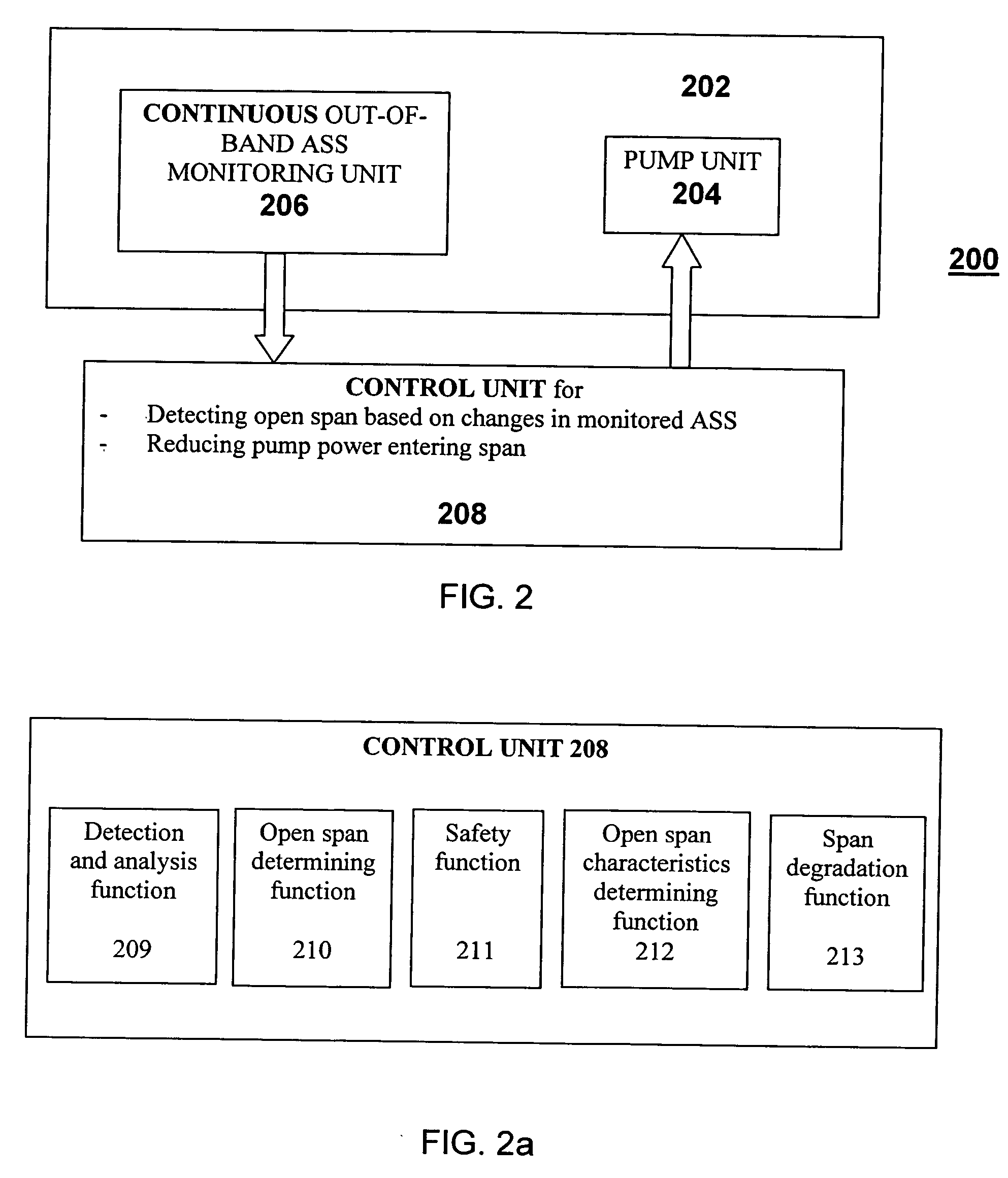
[0044]FIG. 2 shows schematically a preferred embodiment of a distributed Raman amplification system 200 of the present invention. System 200 comprises a Raman pump unit 204 operative to provide a Raman pump energy that comprises one or more Raman pump wavelengths to the span to be amplified (see below), and an apparatus for continuous out-of-band ASS monitoring 206, the monitoring providing an ASS power output. System 200 further comprises a control unit 208 operative to detect and analyze in real-time changes in the ASS power, and upon determination that such changes indicate an open span, reduce the level of the Raman pump energy entering the span to a safe level.

[0045]FIG. 2a shows the control unit 208 in more detail. The control unit includes a detection and analysis function 209 to detect and analyze in real-time changes in the out-of-band ASS power level, an open span determining function 210 to determine whether the change in out-of-band ASS power level indicates an open spa...


PUM


Abstract

A system and method for providing eye-safety protection during operation of distributed Raman amplifiers based on the application of continuous out-of-band amplified spontaneous scattering (ASS) monitoring in an optical communication network span coupled to the Raman amplifier, and real-time detection and analysis of changes in the monitored ASS power level, The system includes at least one Raman pump for introducing Raman energy into the span, a monitoring unit for performing the continuous ASS monitoring, and a control unit operative to detect and analyze in real-time changes in the ASS power, and upon determination that such changes indicate an open span, to reduce the level of the Raman pump energy entering the span to a safe level.

Description

FIELD OF THE INVENTION [0001] The present invention relates generally to optical fiber amplifiers used in fiber optics telecommunications systems. More particularly, the invention relates to Raman optical fiber amplifiers, and to methods and apparatuses for detecting and diagnosing faults in an optical communication system span that utilizes such amplifiers, in order to provide improved eye protection safety. BACKGROUND OF THE INVENTION [0002] Modern optical communication systems utilize optical amplifiers to amplify wavelength division multiplexed (WDM) signal channels as they are transmitted through the system. The first optical amplifiers to be commercially deployed were Erbium doped fiber amplifiers (EDFAs), which are self-contained units placed between 60-120 km length spans of the communication link. These units contain a special Erbium doped fiber (EDF), which serves as the gain medium used to transfer energy from laser diode pumps within the units to the optical signal chann...

Claims


Application Information

Patent Timeline
IPC IPC(8): H01S3/00
CPCH01L31/14H01S3/302H04B10/0777H04B10/2916H04B2210/08
Inventor GHERA, URIBERGER, DANIELFILIBA, ITZHAKMENASHE, DAVID
Owner RED C OPTICAL NETWORKING
Learn More