Semiconductor device and magnetic recording system using the same

a magnetic recording and magnetic technology, applied in the field of magnetic recording systems and magnetic recording devices, can solve the problems of inability to control the duration independently, change in duration, etc., and achieve the effect of shortening the rise time of write current and increasing the recording frequency

Inactive Publication Date: 2006-06-08
HITACHI LTD
View PDF26 Cites 21 Cited by
  • Summary
  • Abstract
  • Description
  • Claims
  • Application Information

AI Technical Summary

Benefits of technology

[0004] There have been requirements for higher recording density and speed increase in recording / reproducing frequency, which have been placed on magnetic recording systems, to record huge amounts of data on a recording medium and to reproduce data from a recording medium in a short period of time. In magnetic recording, a write current, generated by a writing drive circuit (write driver) corresponding to information to be recorded, is applied to the inductive head to generate a recording magnetic field to magnetize a magnetic medium in a specified direction to thereby record information. In this process, by using an overshoot current, the rise time of a write current is shortened and a speed increase in recording frequency can be realized.
[0005] Generally, in the magnetic recording system, an optimum write current waveform, which induces less error rate and less adjacent track interference, differs with an inductive head and magnetic media or a combination of them. For this reason, the write driver should preferably be able to minutely control the overshoot current to obtain an optimum waveform for each system.
[0007] Meanwhile, in the past, longitudinal magnetic recording was in widespread use, in which the medium magnetizing direction is in the plane of the medium, but to meet the requirement of high recording density in recent years, attention is being drawn to perpendicular magnetic recording, in which the medium magnetizing direction is a direction perpendicular to the plane of the medium. In longitudinal magnetic recording, because a write current is normally large, it was possible to curb the error rate and the adjacent track interference to such an extent that there is no problem from a practical standpoint without necessarily performing meticulous control of overshoot current waveform.
[0014] In a magnetic recording system, an optimum write current waveform for magnetic recording differs with an inductive head, a recording medium, and a transmission line connecting the write driver with the inductive head. Because there are a plurality of combinations of the above-mentioned parts when starting up a system, the write driver should preferably be able to generate a plurality of write current waveforms. Even after a combination of the above parts has been decided, an optimum current waveform will change with production variations of individual parts. For this reason, it is desirable not only that the write driver for magnetic recording can generate an optimum write current waveform compatible with several kinds of configuration of the magnetic recording system, but also that waveform control should be possible even to accommodate production variations in a combination of the above parts. Moreover, to increase the speed in recording frequency, the rise time in write current had better be short.
[0015] Since the write driver for magnetic recording according to the present invention is designed to control the amplitude and the duration of an overshoot current independently of each other, it is possible to perform meticulous control of the overshoot, and therefore it is possible to provide a magnetic recording system which records information on a medium in an optimum waveform of the write current.

Problems solved by technology

Therefore, even if a current waveform at the output terminal of the write driver is controlled so that its amplitude and duration are in desired states as shown in FIG. 9, the current becomes slow in rising affected by the load, and duration control is started before the time when the current reaches its peak level, with the result that the duration also changes in a manner following the pattern of the amplitude and it is impossible to control the duration independently.

Method used


Image

  • Semiconductor device and magnetic recording system using the same
  • Semiconductor device and magnetic recording system using the same
  • Semiconductor device and magnetic recording system using the same

Examples


embodiment 1

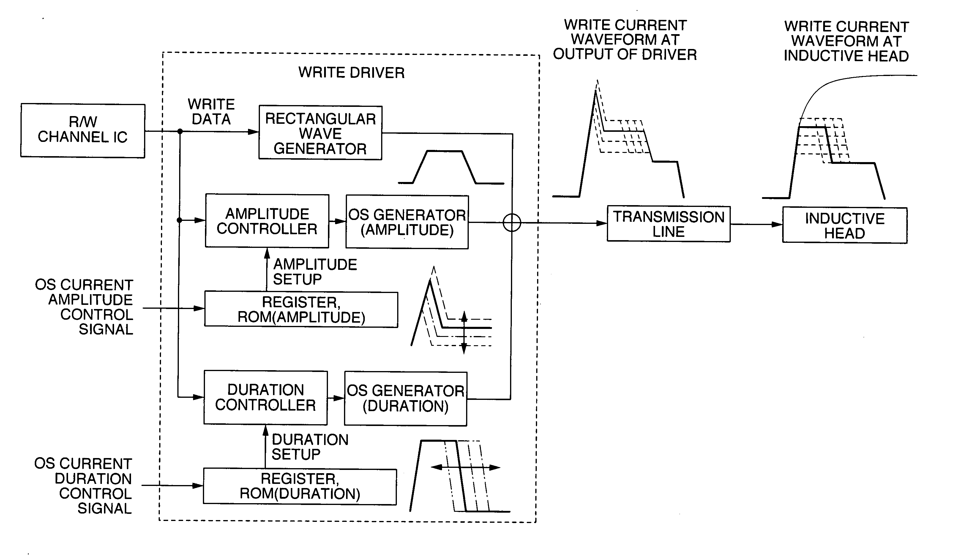
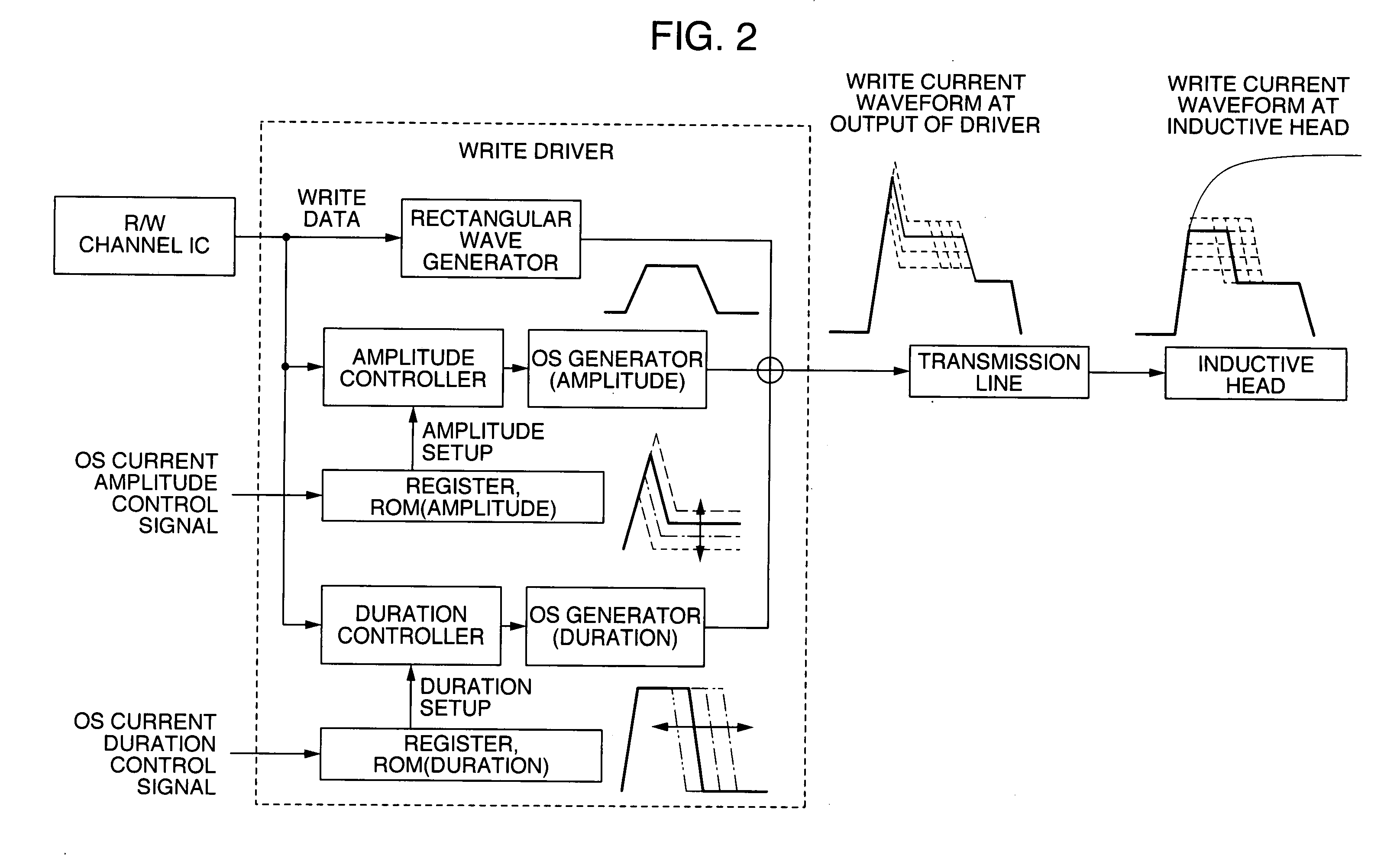
[0029]FIG. 2 is a block diagram showing a structure of a write driver of the present invention and an embodiment of a write signal transmission system of a magnetic recording system using the same write driver. Referring to FIG. 2, description will be made of waveform control of an overshoot (OS) current of a write driver circuit according to this embodiment.

[0030] The overshoot current waveform in the write driver in FIG. 2 represents the current waveforms generated by respective current generator circuits. The upper portion of the waveform at the inductive head is a result of a current waveform from the write driver being rounded by applied load, and the current waveform as illustrated occurs at the inductive head. A control signal is formed by applying settings, stored in a register or a ROM, to write data received from the R / W channel IC. By the control signal, the duration and the amplitude of an overshoot current is controlled, and a resultant signal is sent to the overshoot ...

embodiment 2

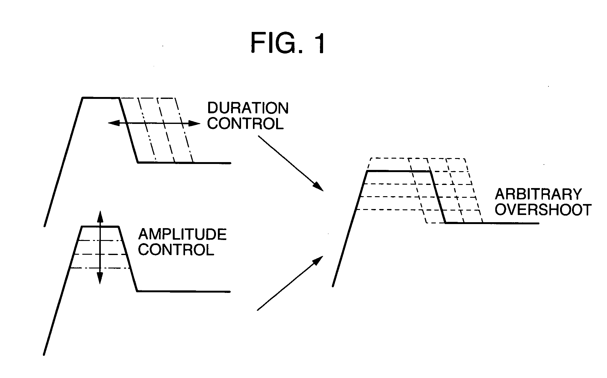
[0036] Description will now be made of another embodiment of the write driver for magnetic recording in the present invention. According to a second embodiment, in a block diagram of FIG. 1, there is further provided a termination circuit which is used to make the impedance of the write driver match the impedance of a transmission line to which the magnetic head is connected. A concrete structure of the termination circuit will be described in detail in a subsequent embodiment.

[0037] According to the second embodiment, the termination circuit serves to reduce reflection waves produced by impedance mismatching between the write driver and the transmission line and also decrease current loss to the termination circuit. By this means, it is possible to suppress distortion of the current waveform due to reflection, and provide an optimum write current waveform.

embodiment 3

[0038] Description will be made of yet another embodiment of the write driver for magnetic recording in the present invention. In a third embodiment, in the block diagram of FIG. 2, a correction circuit is further provided for use in a case where reflection waves are produced by a mismatch between the impedance of the above-mentioned transmission line and the output impedance of the write driver for magnetic recording or by an impedance mismatch between the transmission line and the write head. A concrete example of the circuit for compensating reflection waves will be described in detail in an embodiment which appears later on.

[0039] According to the third embodiment, by using a circuit for compensating reflection waves, it is possible to cancel reflection waves caused by the above-mentioned impedance mismatching. Consequently, an optimum write current waveform can be provided.


PUM

PropertyMeasurementUnit
magnetic fieldaaaaaaaaaa
currentaaaaaaaaaa
write currentaaaaaaaaaa

Abstract

A write driver circuit capable of controlling the waveform of overshoot of a write current, more specifically, controlling a rise, amplitude, and duration of overshoot (OS) in the waveform of an output current independently of one another. The write driver circuit includes transistors for controlling the rise, amplitude, and duration of OS, an impedance matching unit between the write driver and the load, and a canceller of reflection waves from the head.

Description

INCORPORATION BY REFERENCE [0001] The present application claims priority from Japanese application JP 2004-349267 filed on Dec. 2, 2004, the content of which is hereby incorporated by reference into this application. FIELD OF THE INVENTION [0002] The present invention relates to a semiconductor device of a write drive circuit (write driver) of a magnetic recording system, and more specifically relates to a write driver operating in a good condition in a magnetic recording system of perpendicular magnetic recording type. BACKGROUND OF THE INVENTION [0003] As a write driver for a magnetic recording system, there has been one type which changes the amplitude and the timing of an applied overshoot current corresponding to individual write current pulses so that the recording head can correctly record information on a recording medium (JP-A-2004-030730, for example). SUMMARY OF THE INVENTION [0004] There have been requirements for higher recording density and speed increase in recording...

Claims


Application Information

Patent Timeline
Patent Type & Authority Applications(United States)
IPC IPC(8): G11B5/02G11B5/09
CPCG11B5/02
Inventor HAYASHI, YOSHIHIROARAKAWA, FUMIHIKOKUSUNOKI, TAKESHIUENO, SATOSHI
Owner HITACHI LTD
Why Eureka
Try Eureka