
Method and apparatus for implement XANES analysis

a technology of xanes analysis and apparatus, applied in the direction of instruments, liquid/fluent solid measurements, nuclear engineering, etc., can solve the problems of insufficient brightness of conventional laboratory x-ray sources, low conversion efficiency of continuum x-ray generation, and only measurement, etc., to achieve low power, high sensitivity, and low cost

Inactive Publication Date: 2006-06-08
X-RAY OPTICAL SYSTEM INC
View PDF2 Cites 26 Cited by
  • Summary
  • Abstract
  • Description
  • Claims
  • Application Information

AI Technical Summary

Benefits of technology

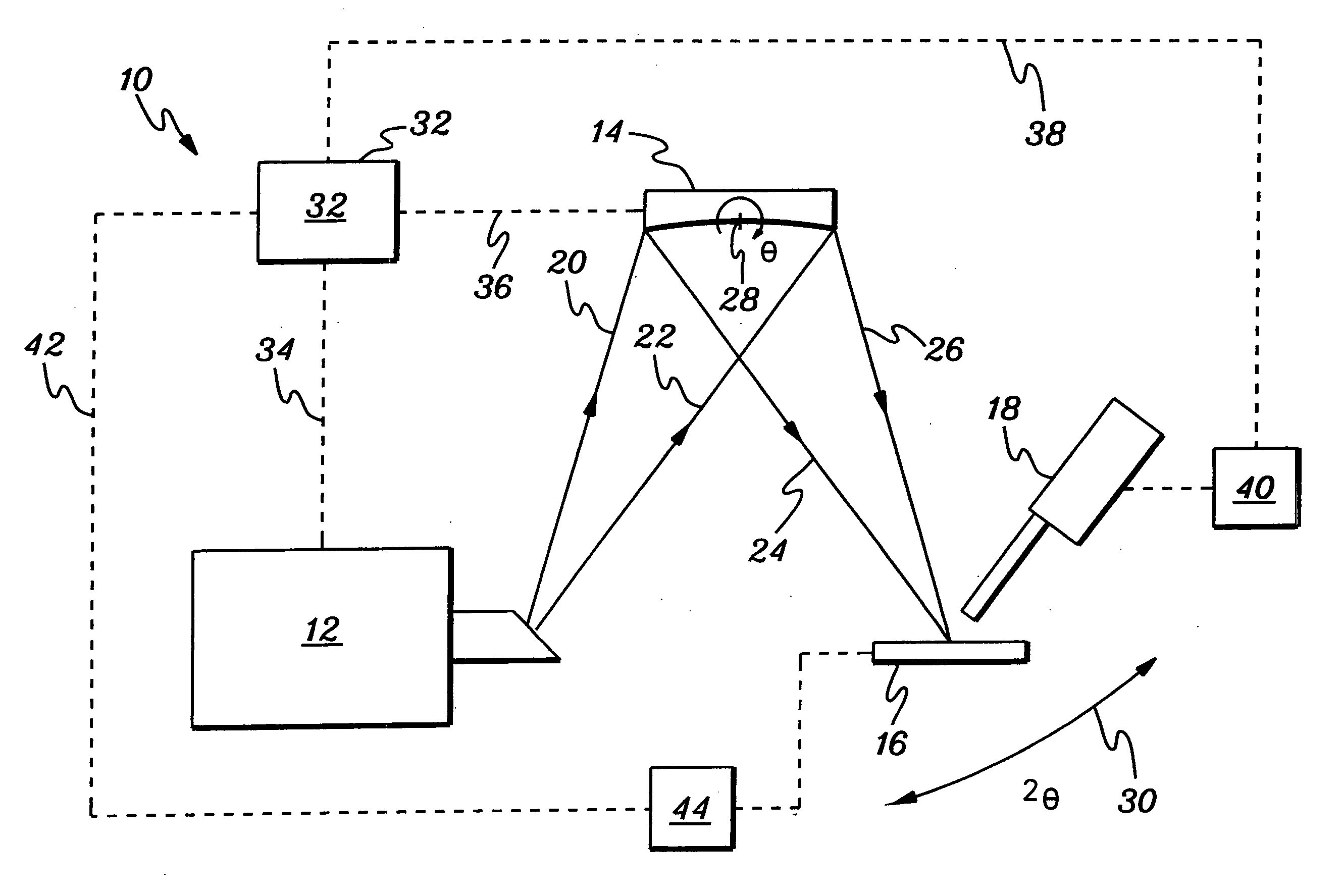
[0013] A compact, high sensitivity, low power and low cost, table-top instrument for implementing XANES measurements will make possible chemical speciation and characterization studies in a broad variety of applications in medicine, science and industry. The present invention provides methods and apparatus for performing XANES analysis which address many of the limitations of prior art methods and apparatus. For example, one aspect of the invention is a system for performing x-ray absorption near-edge structure analysis, the system comprising: means for directing x-rays having a first energy onto a sample; means for detecting x-rays having a second energy emitted by the sample when the sample is exposed to x-rays; and means for varying the first energy of the x-rays directed onto the sample wherein the second energy of the x-rays emitted by the sample varies responsive thereto and wherein information concerning near-edge structure of an x-ray absorption spectrum of the sample can be obtained by analysis in part of the variation in the second energy of the detected x-rays. In one aspect of the invention, the means for directing x-rays comprises an x-ray optic. Due to the high intensity gain and narrow energy bandwidth that can be achieved with a crystal x-ray optic, for example, a toroidal crystal optic, in one aspect of the present invention, the x-ray optic used is a crystal x-ray optic. In another aspect of the invention, the x-ray optic comprises a tunable x-ray optic and wherein the means for varying the first energy of the x-rays directed on the sample comprises means for tuning the tunable x-ray optic, for example, θ-2θ tuning, x-x tuning, or x-2x tuning.
[0020] The various aspects of the present invention provide methods and apparatus for practicing XANES analysis that heretofore were impractical, for example, impractical for small research or scientific laboratories and industrial applications. The limited availability and prohibitive cost of typical x-ray sources required in the prior art for performing XANES analysis, for example synchrotron-based systems, limited the practicality of XANES analysis for the smaller laboratory, field use, or industrial use. In addition, prior art XANES analysis are cumbersome to repeatedly adjust for x-ray energy variation and thus require time-consuming re-adjustment or part substitution. In contrast, several aspects of the present invention facilitate the adjustment or variation of x-ray energy and thus expedite the analysis process.

Problems solved by technology

A major limitation of the application of the XANES technique has been that such measurements have only been carried out at synchrotron facilities where x-ray beams of the required intensity and bandwidth have been available.
Conventional laboratory x-ray sources have very low conversion efficiency for continuum x-ray generation, that is, conventional laboratory x-rays sources are simply not bright enough.
Conventional laboratory x-ray sources are also divergent and typically suffer intensity losses imposed by the inverse square law.
However, the high cost, limited time of use, and typically remote nature of synchrotron sources are not suitable for routine laboratory analysis.
But the Johansson geometry is very difficult to achieve in practice.

Method used


Image

  • Method and apparatus for implement XANES analysis
  • Method and apparatus for implement XANES analysis
  • Method and apparatus for implement XANES analysis

Examples


Embodiment Construction

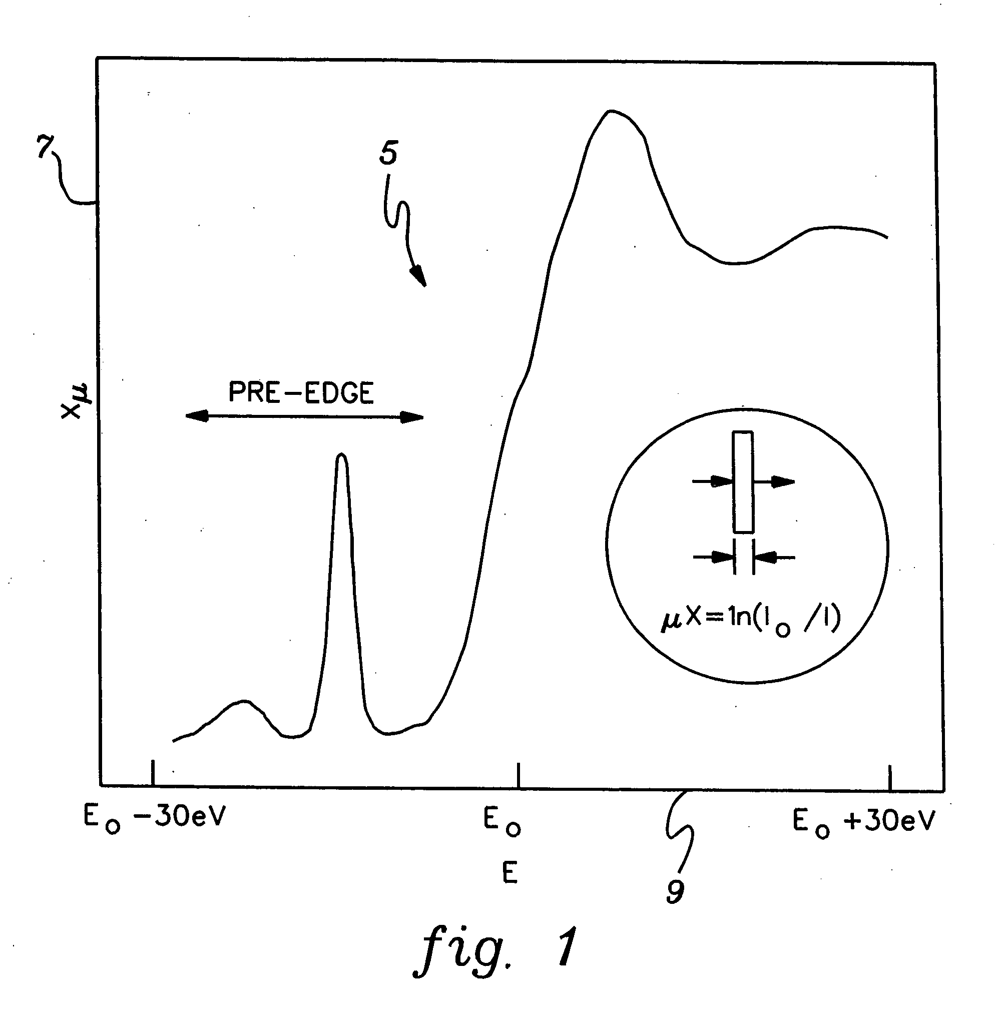
[0031]FIG. 1 illustrates a typical XANES spectrum 5 that can be produced using one aspect of the present invention. The ordinate 7 shown in FIG. 1 represents the intensity of the x-ray fluorescence from a sample. The abscissa 9 of FIG. 1 represents the energy in eV of the corresponding x-ray onto the sample under analysis. EO is the energy of the absorption edge. As shown in FIG. 1, a typical XANES spectrum spans an energy range from about 30 eV below the energy of the absorption edge to about 30 eV above the energy of the absorption edge.

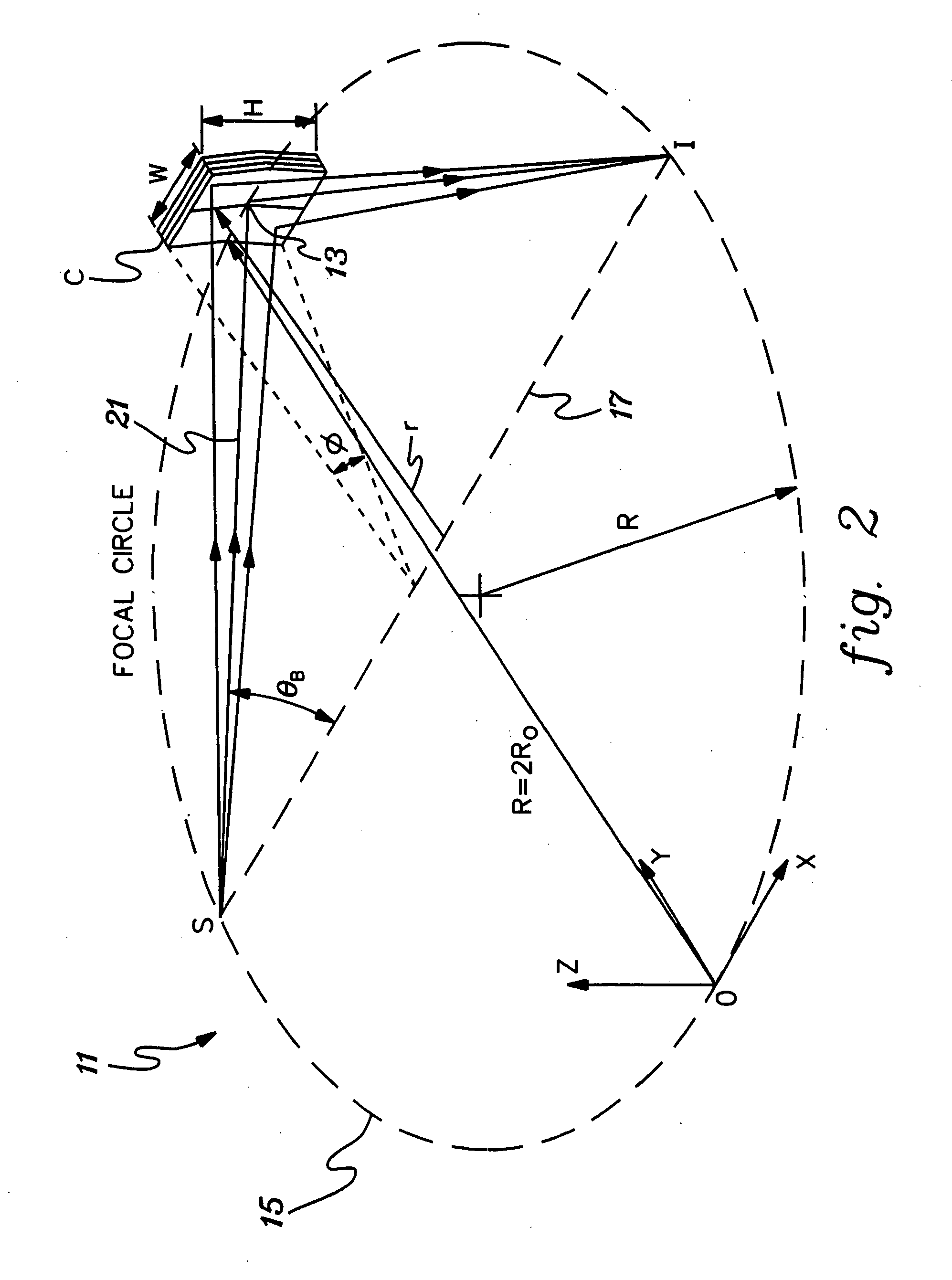
[0032]FIG. 2 is a typical isometric view of a prior art x-ray focusing arrangement 11 having doubly-curved crystal (DCC) optic C, an x-ray source location S, and an x-ray target or image location I, at which the x-ray image is preferably produced. X-rays diverging from a point source S, and striking the surface of crystal C with incident angles within the acceptance rocking curve width of the crystal will be reflected efficiently to target locatio...


PUM


Abstract

Compact, low-power-consuming systems and methods for exposing samples to high-energy radiation, for example, for exposing samples to x-rays for implementing x-ray absorption near edge analysis (XANES). The systems and methods include a low-power-consuming radiation source, such as an x-ray tube; one or more tunable crystal optics for directing and varying the energy of the radiation onto a sample under analysis; and a radiation detecting device, such as an x-ray detector, for detecting radiation emitted by the sample. The one or more tunable crystal optics may be doubly-curved crystal optics. The components of the system may be arranged in a collinear fashion. The disclosed systems and methods are particularly applicable to XANES analysis, for example, XANES analysis of the chemical state of chromium or another transition metal in biological processes.

Description

CROSS-REFERENCE TO RELATED APPLICATIONS [0001] This application is a continuation of PCT Application PCT / US2004 / 017454, filed Jun. 2, 2004, and published under the PCT Articles in English as WO 2004 / 111624 A2 on Dec. 23, 2004. PCT / US2004 / 017454 claimed priority to U.S. Provisional Application No. 60 / 475,148, filed Jun. 2, 2003. The entire disclosures of PCT / US2004 / 017454 and U.S. Ser. No. 60 / 475,148 are incorporated herein by reference in their entirety. In addition, this application contains subject matter which is related to the subject matter of the following application, which is hereby incorporated herein by reference in its entirety: [0002]“An Optical Device for Directing X-rays having a Plurality of Optical Crystals” by Chen, U.S. Ser. No. 60 / 400,809, filed Aug. 2, 2002 (Attorney Docket 0444.048P).STATEMENT REGARDING GOVERNMENT RIGHTS [0003] This invention was made with U.S. Government support under Grant 5R44CA088678-03 awarded by the National Institutes of Health. According...

Claims


Application Information

Patent Timeline
IPC IPC(8): G21K1/06G01N23/06
CPCG01N23/02G01N23/06G21K2201/062G21K2201/064G01N23/083
Inventor CHEN, ZEWUGIBSON, WALTER
Owner X-RAY OPTICAL SYSTEM INC
Learn More