Projection optical system, exposure apparatus, and exposure method
a projection optical system and optical system technology, applied in the field of catadioptric projection optical system, exposure apparatus, exposure method, can solve the problems of increasing the scale of the projection optical system, inability to avoid an increase in the scale of the reflecting optical member, and more difficult to implement optical, etc., to achieve good suppression of reflection loss on optical surfaces, excellent imaging performance, and large effective image-side numerical apertur
- Summary
- Abstract
- Description
- Claims
- Application Information
AI Technical Summary
Benefits of technology
Problems solved by technology
Method used
Image
Examples
first example
[0171]FIG. 5 is an illustration showing a lens configuration of the projection optical system according to the first example of the present embodiment. With reference to FIG. 5, in the projection optical system PL according to the first example, the first imaging optical system G1 is composed of the following components arranged in order from the reticle side along the traveling direction of light: a biconvex lens L11 whose convex surface of aspherical shape is kept toward the wafer; a biconvex lens L12; a negative meniscus lens L13 whose concave surface of aspherical shape is kept toward the reticle; and a first concave reflecting mirror CM1. In the first imaging optical system G1, a reflecting surface of second concave reflecting mirror CM2 for reflecting the light reflected by the first concave reflecting mirror CM1 and transmitted by the negative meniscus lens L13, toward the second imaging optical system G2 is placed in a region not including the optical axis AX between the bic...
second example
[0179]FIG. 7 is an illustration showing a lens configuration of the projection optical system according to the second example of the present embodiment. With reference to FIG. 7, in the projection optical system PL according to the second example, the first imaging optical system G1 is composed of the following components in order from the reticle side along the traveling direction of light: a biconvex lens L11 whose convex surface of aspherical shape is kept toward the wafer; a biconvex lens L12; a negative meniscus lens L13 whose concave surface of aspherical shape is kept toward the reticle; and a first concave reflecting mirror CM1. In the first imaging optical system G1, a reflecting surface of a second concave reflecting mirror CM2 for reflecting the light reflected by the first concave reflecting mirror CM1 and transmitted by the negative meniscus lens L13, toward the second imaging optical system G2 is placed in the region not including the optical axis AX between the biconv...
third example
(Specifications)
[0216] Image-side NA: 1.20
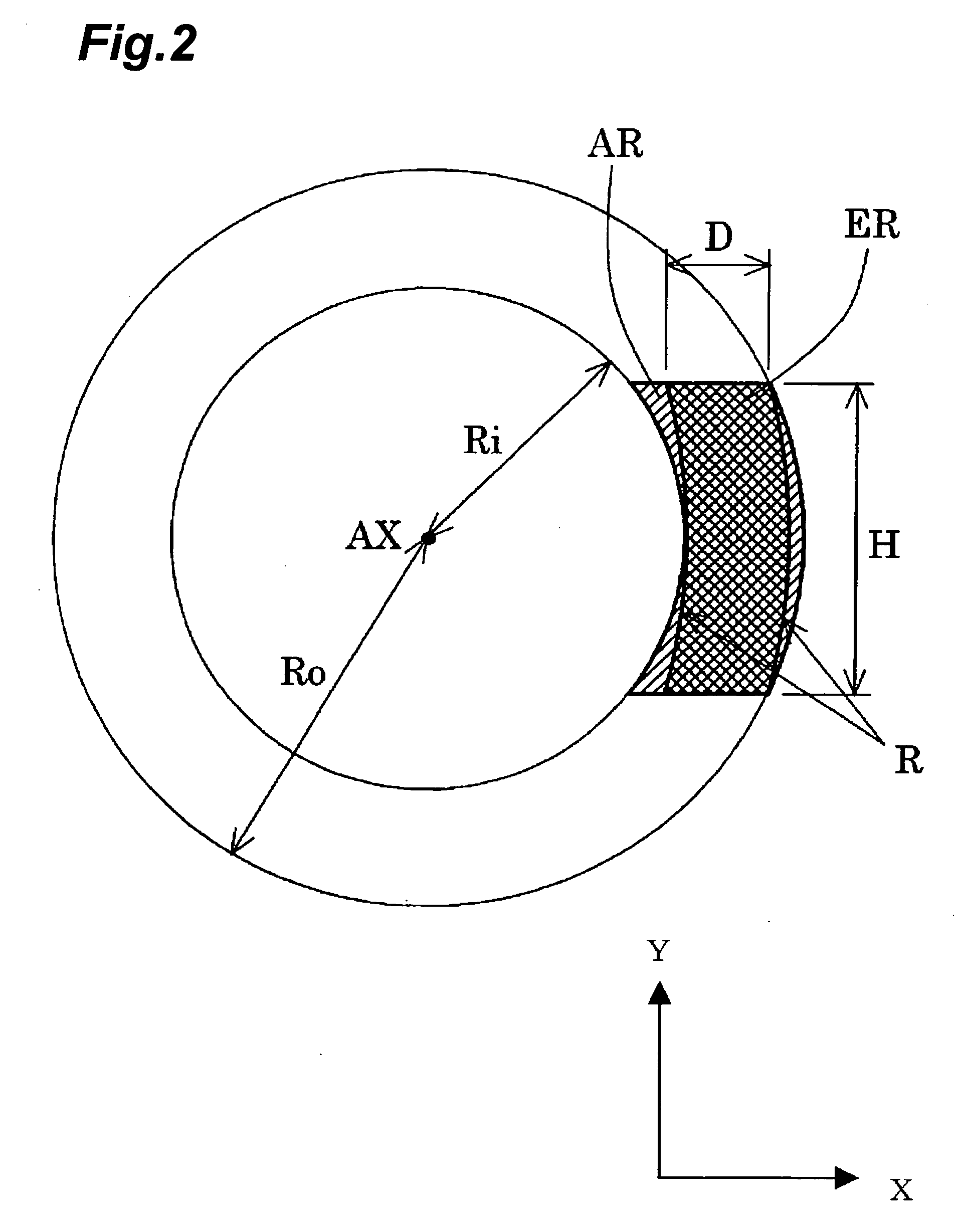
[0217] Exposure area: A=14 mm B=18 mm H=26.0 mm C=4 mm
[0218] Imaging magnification: ¼
[0219] Center wavelength: 193.306 nm
[0220] Refractive index of silica: 1.5603261
[0221] Refractive index of fluorite: 1.5014548
[0222] Refractive index of liquid 1:1.43664
[0223] Dispersion of silica (dn / dλ): −1.591E−6 / pm
[0224] Dispersion of fluorite (dn / dλ): −0.980E−6 / pm
[0225] Dispersion of liquid 1 (dn / dλ): −2.6E−6 / pm
[0226] Values corresponding to Condition Ma=374.65 mm L=1400 mm
TABLE 3(Specifications of Optical Members)#2#3#4#1∞50.0000 1:∞8.0000#5 2:∞33.0000 3:ASP125.0422#5 4:−163.965211.0000 5:355.3161760.7391#5 6:−261.841151.0000 7:277.3335429.0109#5 8:ASP2224.5285 9:−176.6187220.0000#510:−515.6071010.461411:ASP3−10.4614#612:−515.60710−20.0000#513:−176.61872−204.528514:ASP4518.3706#615:−517.39842−241.3807#616:−652.07494171.3807#617:ASP520.0000#518:171.5938241.474319:−245.9452520.0000#520:ASP695.141521:ASP728.3218#522:−273.722611.000023:578.316...
PUM
 Abstract
Description
Claims
Application Information
 - R&D
- Intellectual Property
- Life Sciences
- Materials
- Tech Scout
- Unparalleled Data Quality
- Higher Quality Content
- 60% Fewer Hallucinations
Browse by: Latest US Patents, China's latest patents, Technical Efficacy Thesaurus, Application Domain, Technology Topic, Popular Technical Reports.
© 2025 PatSnap. All rights reserved.Legal|Privacy policy|Modern Slavery Act Transparency Statement|Sitemap|About US| Contact US: help@patsnap.com


