Methods and systems for fluid delivery
- Summary
- Abstract
- Description
- Claims
- Application Information
AI Technical Summary
Benefits of technology
Problems solved by technology
Method used
Image
Examples
example 1
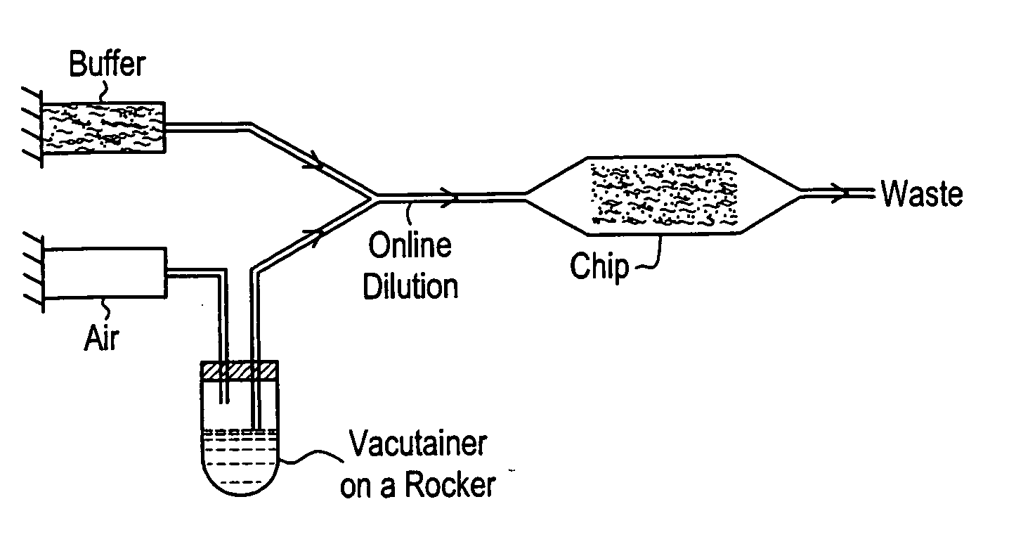
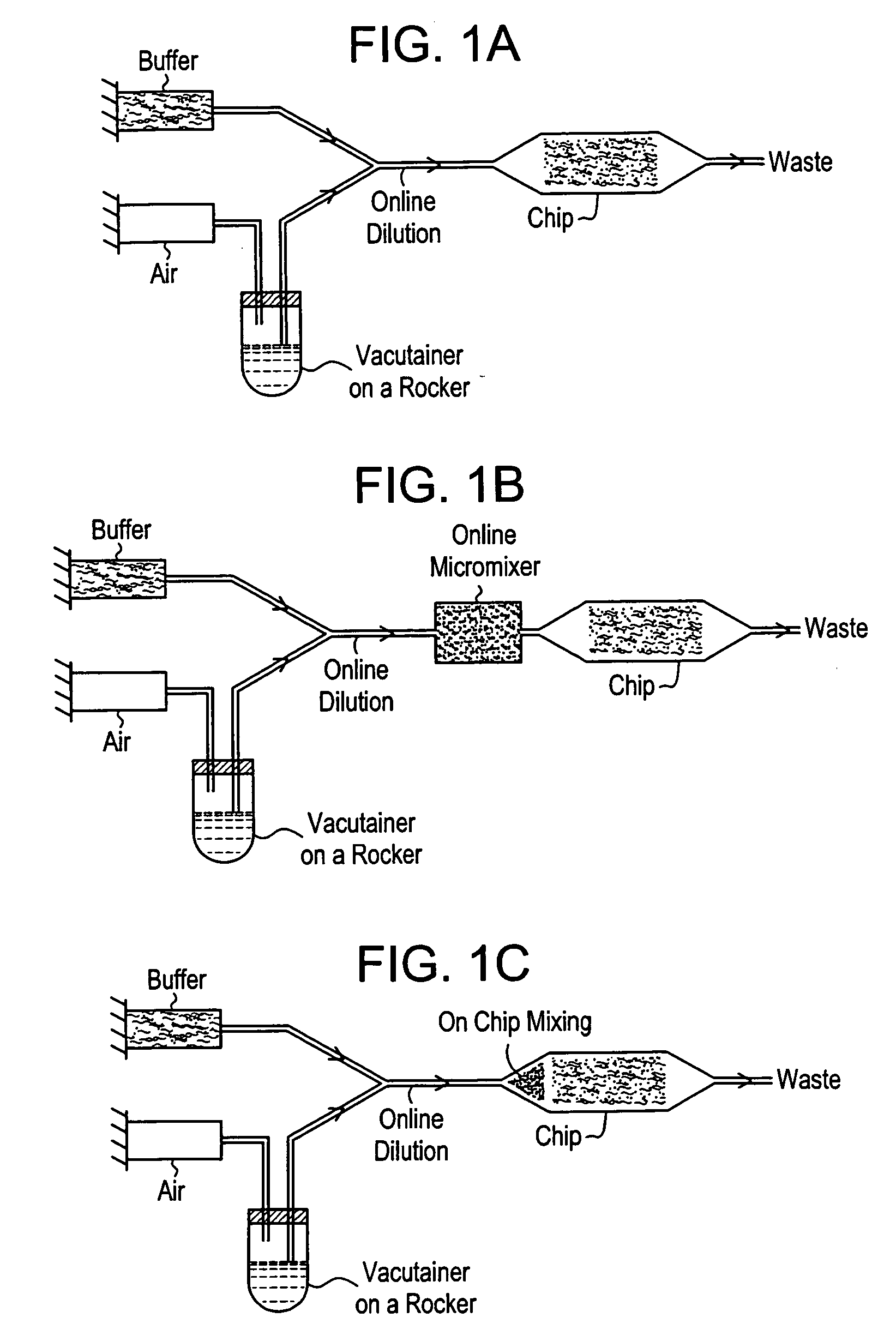
[0049] This system is described with reference to FIGS. 1a-1c. The system is based on positive displacement of blood from a sample container with inline dilution, control of sedimentation, and optional enhancement of mixing. A positive displacement pump, e.g., a syringe pump, drives a pressurizing fluid, such as air or immiscible oil, into the sample container through an inlet, e.g., a needle penetrating a septum. This influx of fluid displaces blood through an outlet, e.g., a second needle penetrating the septum (FIG. 1a). In order to enable extraction of the majority of the blood sample from the sample container, the outlet is preferably long enough to reach the bottom of the tube. Sedimentation is prevented by mechanically rocking the container through an angle of slightly less than 180°, such that the tip of the inlet does not contact the blood. This arrangement avoids entrainment of pressurizing fluid in the blood to be delivered to an analytical device. Diluent may be supplied...
example 2
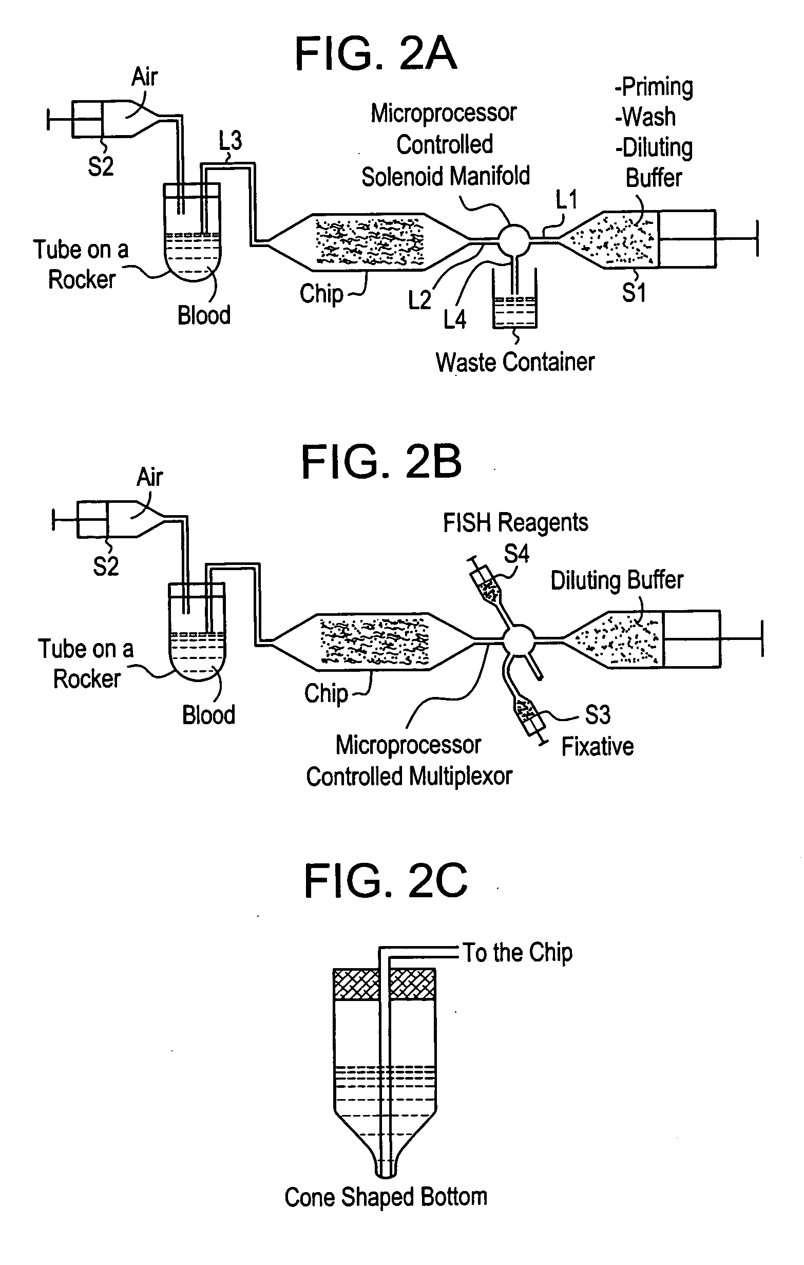
[0050] The system is based on the serial fluidic connection of a blood container, an analytical device, and a diluent reservoir. The system makes use of both inlet and outlet connections to the analytical device to enable priming or wetting of the device while diluting the blood sample to any desired volume. FIG. 2a is a schematic representation of the system. The system is operated as follows: a mechanical rocker holds a blood sample in the sample container, diluent from the reservoir is pushed by a positive displacement pump (S1) into the sample container through line L1, a fluidic switch, e.g., a microprocessor controlled solenoid manifold, actuated to block flow to L4, L2, the analytical device, e.g., a microfluidic device, and L3 at a chosen flow rate to enable priming of the device and timely dilution of the blood. The flow rates may range from 0.1-200 ml / hr. Once the blood is diluted to the desired volume, the pumping of S1 is terminated, the diluted blood sample is then pump...
example 3
[0051] With reference to FIG. 3, another embodiment of the device, which is designated as a “chip,” disposes the blood in a sample container, e.g., a syringe, S2 and the diluent in another container, e.g., a second syringe, S1. S1 is connected to one port of an analytical device, and S2 is connected to another port of the device. Diluent is pumped through the device by displacement, e.g., a combination of push and pull of syringes. The diluent primes the device and dilutes the blood in S2. S2 may be in constant rotation to aid in mixing of the blood and buffer and to prevent cell sedimentation in the container during processing. A coupler may be employed to prevent rotation induced twisting of the fluid line connecting S2 to the device. At least a portion of the diluted blood sample is then passed through the device and into S1.
PUM
 Abstract
Description
Claims
Application Information
 - R&D
- Intellectual Property
- Life Sciences
- Materials
- Tech Scout
- Unparalleled Data Quality
- Higher Quality Content
- 60% Fewer Hallucinations
Browse by: Latest US Patents, China's latest patents, Technical Efficacy Thesaurus, Application Domain, Technology Topic, Popular Technical Reports.
© 2025 PatSnap. All rights reserved.Legal|Privacy policy|Modern Slavery Act Transparency Statement|Sitemap|About US| Contact US: help@patsnap.com


