Rotary vane engine and thermodynamic cycle

Inactive Publication Date: 2006-06-15
AKMANDOR IBRAHIM SINAN +1
View PDF16 Cites 6 Cited by
  • Summary
  • Abstract
  • Description
  • Claims
  • Application Information

AI Technical Summary

Benefits of technology

[0007] One of the objects of this invention, is to increase the thermal efficiency above levels reached by today's heat engines. This is achieved by implementing a longer power extraction phase (151eh, 151fh, 151gh) and by realising high compression ratios with less shaft power input, by processing the fluid through a smooth crescent shape constriction (72 and 49 and 53). Another object of the pr

Problems solved by technology

One reason for the lack of industrial attention is that many rotary engines have been faced by serious wear and sealing deficiencies.
The main cause of the wear is the centrifugal force generated during high speed rotation that forces the vanes to scrap the inner peripheral of the working chamber.
While correcting the wear problem, the number of moving parts has increased and hence, the system became more complex.
At worst, each one of said parts increases the probability of engine failure due to wear and fatigue.
At best, the pressure sealing, lubrication and cooling capabilities of the vane mechanism deteriorates.
Furthermore, above-mentioned prior arts do not have any central vane retention mech

Method used


Image

  • Rotary vane engine and thermodynamic cycle
  • Rotary vane engine and thermodynamic cycle
  • Rotary vane engine and thermodynamic cycle

Examples


Embodiment Construction

[0021] The embodiments of the invention for which an exclusive privilege or property is claimed are described as follows:

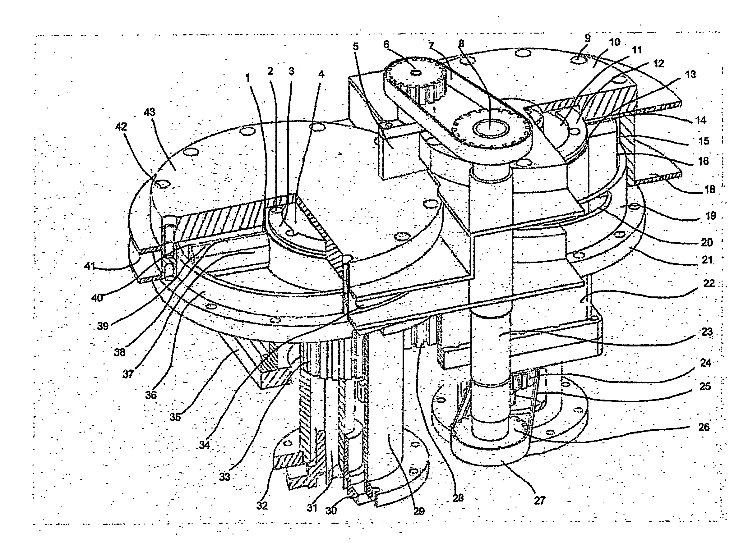
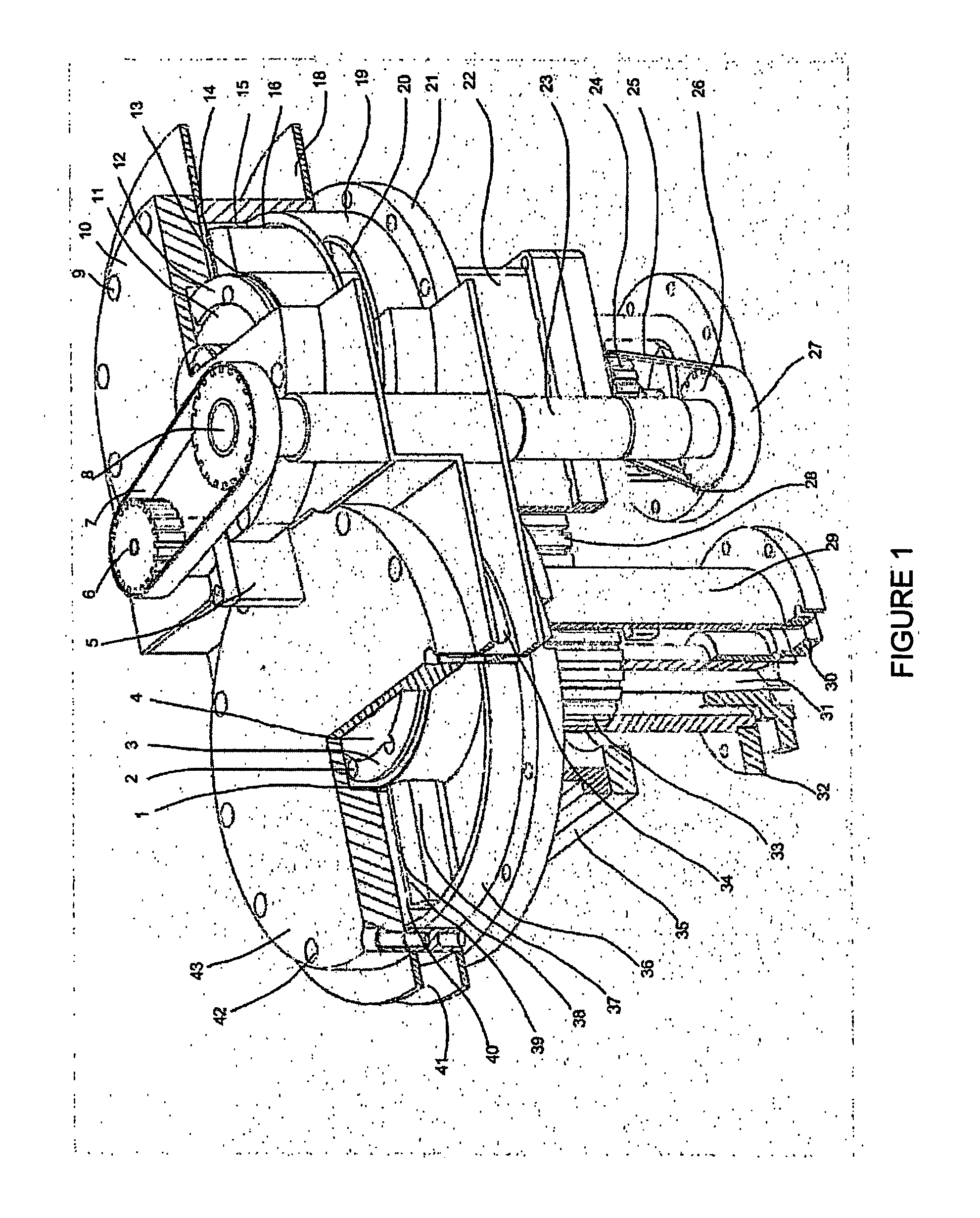
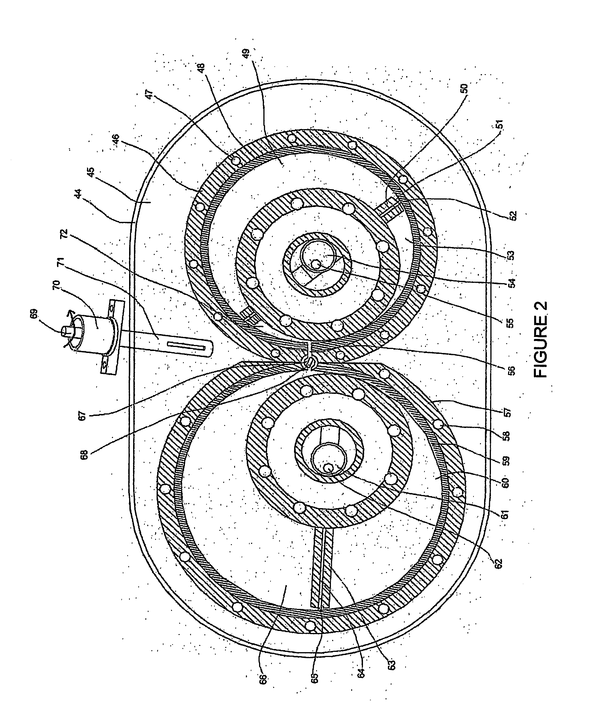
[0022]FIG. 1 and FIG. 2 depict a preferred embodiment of the internal combustion rotary engine where combustion occurs within the turbine chamber (66). FIG. 3 depicts a different preferred embodiment of an external combustion (74, 92) rotary engine where combustion starts in a chamber (72) prior to entry within the turbine expansion chamber (103). The rotary combustion engine casing (14, 21, 35, 44) comprises at least one rotary compressor unit wherein, said unit has inner (19, 48) and outer (46) housings. The engine casing also comprises at least one rotary turbine unit wherein, said unit has inner (59) and outer (57) housings. Said housings are surrounded by a liquid cooled jacket (18, 41, 45). For example, water may be used as coolant. The housings have each, a circularly cylindrical (3, 13) rotor (12, 128), rotatably and eccentrically mounted. The said rotary...


PUM


Abstract

For low mass flow, the solo use of the turbo-rotary engine overcomes the limitations of conventional internal combustion engines and enable significant improvement in power, torque and efficiency. The solo configurations (FIG. 1, 2, 3, 4) of the invention comprise compressor (48) and turbine housings (59), each housing receiving an eccentrically placed rotor (135), equipped by a single sliding vane (50, 63). Contact wear of the sliding vane tips (86, 109) with the chamber non-circular cycloidal peripheral (88, 97), is eliminated by a pivot axle vane retention mechanism (139, 150). For high mass flow rate, a compound configuration (FIGS. 8, 9, 10) of rotary compressors and turbines with conventional gas turbine engine components. Allows an improvement in efficiency and performance. Conventional long and heavy concentric main shafts are eliminated. In this invention, rotary turbines drive compressors (158), fans (153), propellers and rotary wings (186). In return, the conventional turbines (171) drives a plurality or rotary compressors (164, 166, 168). The compound engine of the invention combines the thermal efficiency of the rotary internal engine cycle (151) and the high mass flow, high power, compact size and light weight of the gas turbine engines.

Description

FIELD OF THE INVENTION [0001] This invention relates to energy systems and more particularly to componentry and thermodynamic cycle for enabling shaft work, propulsion drive, electric power source, jet propulsion and thermodynamic systems such as ventilation, cooling, heat, pressure or vacuum generating systems. BACKGROUND OF THE INVENTION [0002] Since the start of the industrial revolution, the reciprocating piston engine based on the Otto and Diesel cycles and, the gas turbine engine based on the Brayton cycle, have largely dominated the market. Despite this fact, for many years,.patents on rotary combustion engines have claimed that rotary engines possess many advantages over reciprocating engines such as having high torque, fewer parts, lower weight and fewer reciprocating imbalance. Fundamental design characteristics is of the present invention addresses the main problems related to rotary engines and bridges the mass flow and rotational speed gaps between reciprocating and gas...

Claims


Application Information

Patent Timeline
IPC IPC(8): F02B53/04F01C1/344F01C11/00F01C13/00F01C21/08F01C21/10F02C3/055
CPCB64C27/12F01C1/3442F01C11/004F01C11/008F01C13/00F01C21/0836F01C21/106F02C3/055F04C2250/301Y02E20/16F05D2220/32
Inventor AKMANDOR, IBRAHIM SINANERSOZ, NAZMI
Owner AKMANDOR IBRAHIM SINAN
Why Eureka
Try Eureka