
Boot for constant velocity universal joint

a universal joint and constant velocity technology, applied in the field of boots, can solve the problems of difficult to form the inner peripheral surface of the major-diameter cylinder of the boot, difficult to secure the sealing ability, and limited durability of the rubber, so as to maintain the sealing ability and reduce the resistan

Active Publication Date: 2006-06-15
TOYODA GOSEI CO LTD
View PDF1 Cites 7 Cited by
  • Summary
  • Abstract
  • Description
  • Claims
  • Application Information

AI Technical Summary

Benefits of technology

[0012] The present invention has been developed in view of the aforementioned circumstances. It is therefore an object of the present invention to provide a boot for a constant velocity universal joint, boot which can maintain the sealing ability high and at the same time can reduce the resistance during its fitting around a mating member, and additionally which can furthermore produce a fitting completion feeling when the fitting is completed.
[0031] In accordance with the present invention, the present boot for a constant velocity universal joint comprises a plurality of the flanges, which extend axially outward from an opposite end surface of the major-diameter cylinder, and the positioning protrusions which are formed on the flanges to protrude radially inward. Accordingly, the positioning protrusions are disposed outside a fastening allowance of the fastening member so that they do not affect the sealing ability of the major-diameter cylinder. Moreover, the flanges are formed in a cantilevered manner, and are disposed axially off or away from positions, which are demarcated by the noncircular inner peripheral cross-section of the major-diameter cylinder. Consequently, the flanges deform elastically in radial directions with ease, without being restricted by the major-diameter cylinder. Therefore, the present boot exerts reduced load during its fitting around the mating member. In addition, when the positioning protrusions reach positions at which the concavities of the mating member are disposed, the flanges restore their original shapes with large elastic reaction forces. As a result, the present boot produces a favorable fitting completion feeling, and enables an assembly operator to securely carry out the positioning.

Problems solved by technology

However, since rubber exhibits limitation in view of the durability, thermoplastic elastomer, which is good in terms of the weatherability, heat resistance and fatigue resistance, has been used recently.
Due to the circumstances, there has been a problem in that it is difficult to secure the sealing ability, because thermoplastic elastomer, the material for forming a boot, exhibits low elasticity so that it does not exhibit following ability as good as rubber.
When manufacturing such a boot by blow molding, however, it is difficult to form the inner peripheral surface of the boot's major-diameter cylinder so as to enhance the sealing ability with respect to the mating member.
Thus, from the manufacturing viewpoint as well, it is difficult to secure the sealing ability.
However, since the major-diameter cylinder is relatively hard, the diametrically-enlarging deformation of the major-diameter cylinder might be restricted when the positioning protrusions slide on the outer peripheral surface of the mating member during the fitting of the boot around the mating member.
Accordingly, there has been a problem in that the major-diameter cylinder might resist to the fitting of the boot around the mating member to degrade the operability.
Moreover, even when the positioning protrusions engage with the concavities of the mating member during the fitting of the boot around the mating member, the deformation magnitude of the major-diameter cylinder is scant so that no fitting completion feeling might be obtained.
Consequently, there has been a drawback that no checking might be made whether the boot is positioned with respect to the mating member.
In this instance, however, since the sealing protrusion rims slide on the mating member when fitting the boot around the mating member, the sealing protrusion rims might be worn off or damaged.
If such is the case, the boot might suffer from a drawback in view of the sealing ability.
However, it is less likely to obtain a fitting completion feeling when the positioning protrusions engage with the mating member's concavities.
Moreover, when considering employing such a construction for a boot for a constant velocity universal joint, boot which comprises a boot body and a grommet, it is not recommendable to form the slits in the grommet or major-diameter cylinder from the viewpoint of the sealing ability, in addition to the problem of the poor fitting completion feeling.
Besides, there arises a problem in that the man-hour requirements are enormous for manufacturing such a boot.

Method used


Image

  • Boot for constant velocity universal joint
  • Boot for constant velocity universal joint
  • Boot for constant velocity universal joint

Examples


examples

[0049] Hereinafter, the present invention will be described in detail with reference to examples of the present invention.

example no.1

Example No. 1

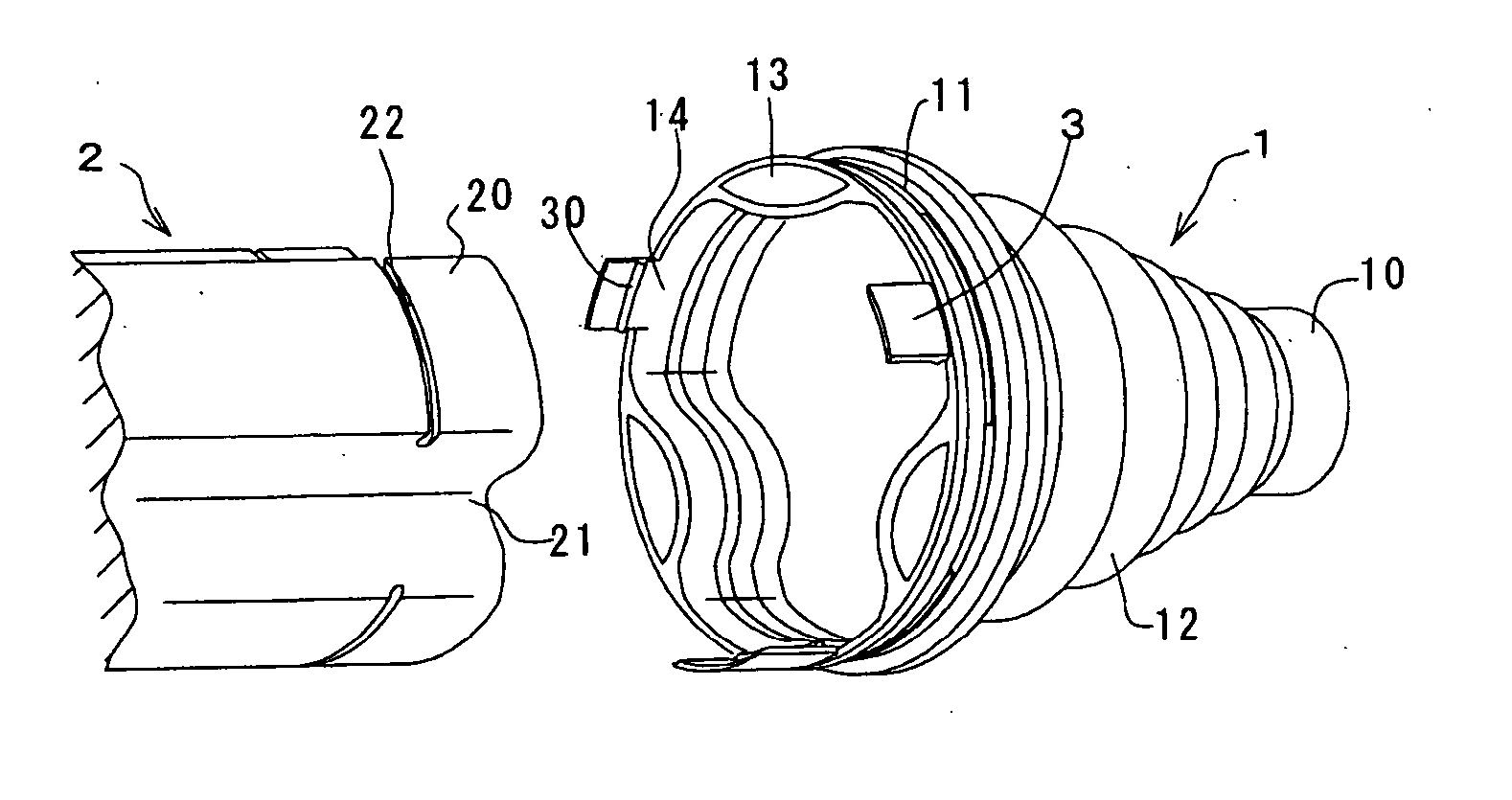
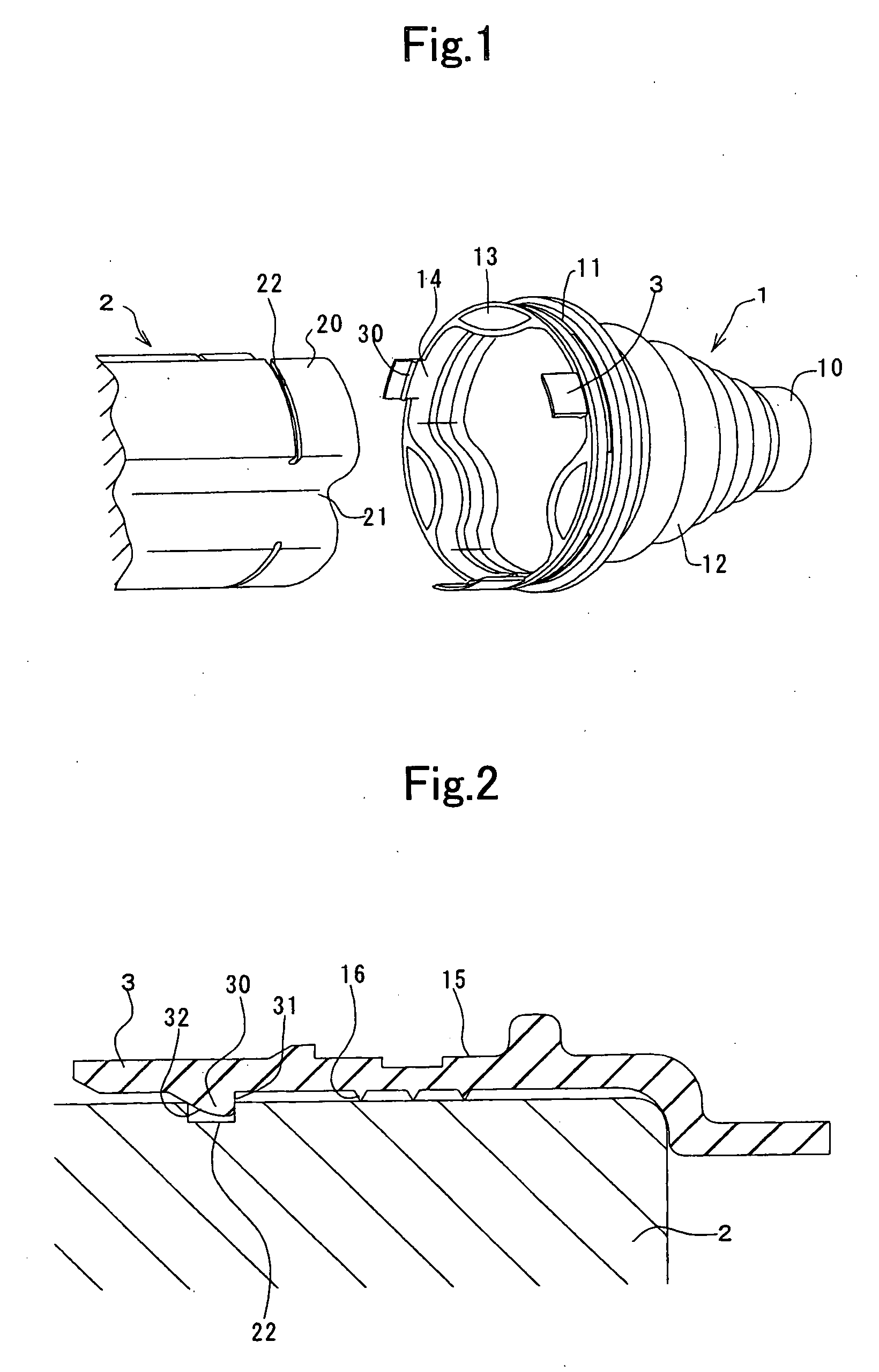
[0050]FIG. 1 illustrates a boot of Example No. 1 according to the present invention for a constant velocity universal joint, along with a mating member, in a perspective diagram. FIG. 2 illustrates a major part of the boot, which is fitted around the mating member, in an enlarged cross-sectional diagram. The boot comprises a boot body 1, and is formed of relatively hard thermoplastic elastomer by injection blow molding.

[0051] The boot body 1 comprises a minor-diameter cylinder 10, a major-diameter cylinder 11, and a bellows 12. The major-diameter cylinder 11 has a larger diameter than that of the minor-diameter cylinder 10. The bellows 12 connects the minor-diameter cylinder 10 with the major-diameter cylinder 11 integrally, and is formed as a substantially truncated cone shape. The major-diameter cylinder 11 has an outer peripheral surface which is formed as a perfect circle, but has an inner peripheral surface which is formed irregularly so as to conform to an outer ...

example no.2

Example No. 2

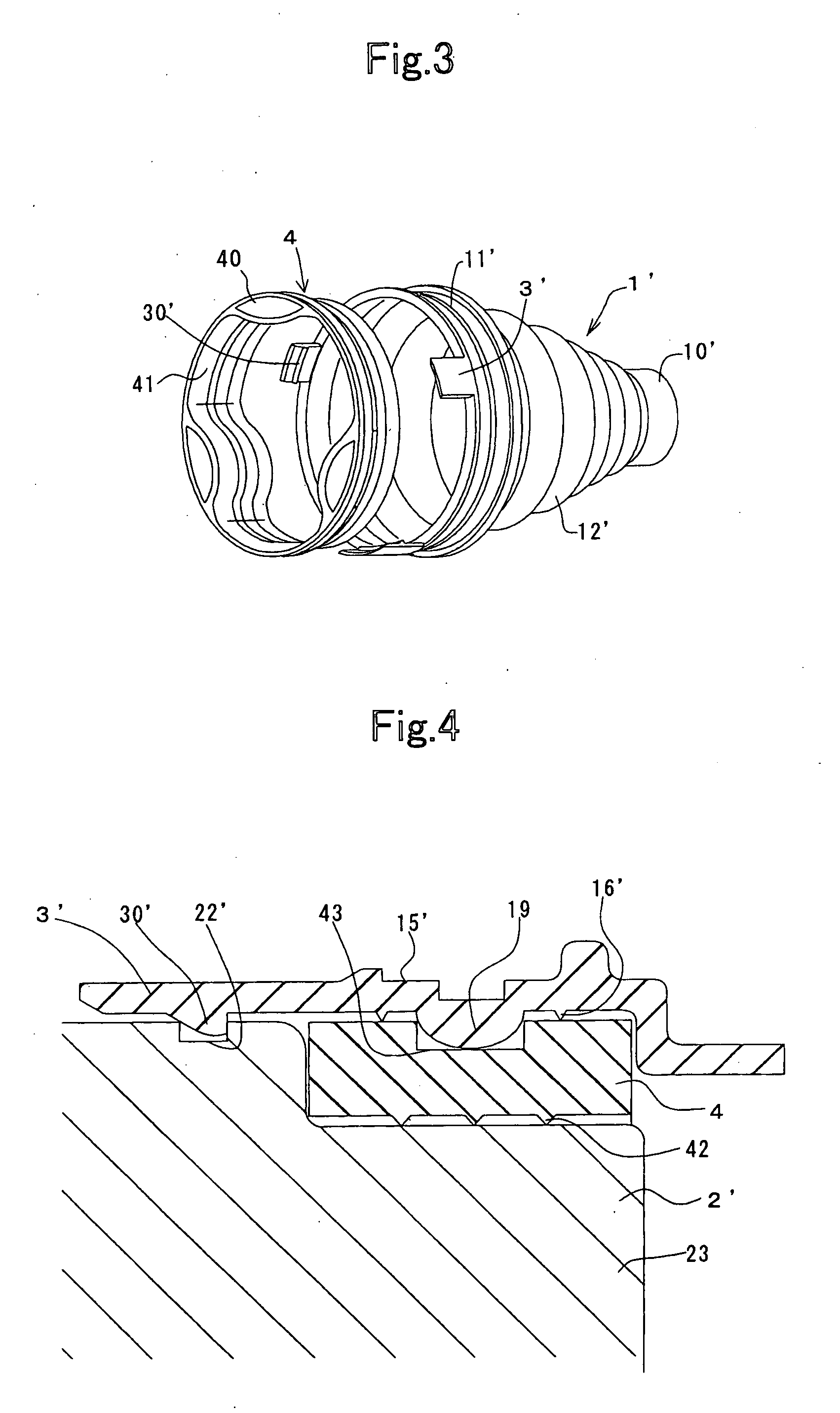
[0061]FIGS. 3 and 4 illustrate a boot according to Example No. 2 of the present invention for a constant velocity universal joint. The boot according to Example No. 2 comprises a boot body 1′, and an annular grommet 4. The grommet 4 is fitted into a major-diameter cylinder 11′ of the boot body 1′. The boot body 1′ is formed of relatively hard thermoplastic elastomer by injection blow molding. The grommet 4 is formed of rubber or relatively soft thermoplastic elastomer by injection molding.

[0062] The boot body 1′ comprises a minor-diameter cylinder 10′, a major-diameter cylinder 11′, and a bellows 12′. The major-diameter cylinder 11′ has a larger diameter than that of the minor-diameter cylinder 10′. The bellows 12′ connects the minor-diameter cylinder 10′ with the major-diameter cylinder 11′ integrally, and is formed as a substantially truncated cone shape. The major-diameter cylinder 11′ has an inner peripheral surface on which a ring-shaped protrusion rim 19 is forme...


PUM


Abstract

A boot for a constant velocity universal joint includes a minor-diameter cylinder, a major-diameter cylinder, and a bellows. The major-diameter cylinder includes a sealing protrusion rim, a plurality of flanges, and positioning protrusions. The sealing protrusion rim is formed on an inner peripheral surface of the major-diameter cylinder. The flanges are disposed at intervals in a peripheral direction of the major-diameter cylinder, and extend axially outward from an opposite end surface of the major-diameter cylinder. The positioning protrusions protrude from the flanges radially toward an inner peripheral side of the major-diameter cylinder, and are to be engaged with concavities formed in an outer peripheral surface of the mating member. The boot maintains the sealing ability high, and at the same time can reduce the resistance during its fitting around a mating member, and can furthermore produce a fitting completion feeling when the fitting is completed.

Description

BACKGROUND OF THE INVENTION [0001] 1. Field of the Invention [0002] The present invention relates to a boot which covers constant velocity universal joints, which are essential for joints for the drive shaft of front wheel drive vehicles, to inhibit water and dust from intruding into the joint part of constant velocity universal joints. [0003] 2. Description of the Related Art [0004] The joint part of a constant velocity universal joint has been covered with a bellows-shaped boot, in which grease is sealed, conventionally. The boot inhibits water and dust from intruding into the joint part, thereby keeping the joint part rotating smoothly at large angles. Such a boot for a constant velocity universal joint comprises a major-diameter cylinder, a minor-diameter cylinder, and a substantially-truncated-cone-shaped bellows. The major-diameter cylinder is held to a joint outer race. The minor-diameter cylinder has a smaller diameter than that of the major-diameter cylinder, and is held to...

Claims


Application Information

Patent Timeline
Patent Type & Authority Applications(United States)
IPC IPC(8): F16J3/00
CPCF16J3/042F16D3/2055F16D3/845
Inventor TORIUMI, MAYUKI
Owner TOYODA GOSEI CO LTD
Learn More