Electrostatic actuator, droplet discharge head and method for manufacturing the droplet discharge head, droplet discharge apparatus, and device

a technology of electrostatic actuators and droplets, which is applied in the direction of printing, etc., can solve the problems of reducing the withstand voltage of the insulating film, the inability to further improve the pressure and insulation resistance, and the direct application of the electrostatic actuator to the insulating film cannot meet both the increase in the generated pressure and the increase in the insulation resistance. , to achieve the effect of reducing the driving voltage of the actuator, reducing the surface charge, and high durability

Inactive Publication Date: 2006-06-15
SEIKO EPSON CORP
View PDF17 Cites 17 Cited by
  • Summary
  • Abstract
  • Description
  • Claims
  • Application Information

AI Technical Summary

Benefits of technology

[0049] Furthermore, a method for manufacturing a droplet discharge head according to the present invention includes the steps of forming an insulating film by laminating a cap layer for preventing impurities in a diaphragm from diffusing and a dielectric film formed of a substance having a higher relative dielectric constant than silicon oxide on the surface of a cavity substrate on which the diaphragm is formed, etching the cavity substrate including the insulating film to form a droplet discharge chamber including the diaphragm, bonding the cavity substrate including the droplet discharge chamber with an electrode substrate including a counter electrode in correspondence with the diaphragm while the diaphragm and the counter electrode face each other, and bonding a nozzle substrate to an opening surface of the cavity substrate.
[0050] These methods make it possible to manufacture a small electrostatic actuator with high durability in which an adequate withstand voltage between the diaphragm and the counter electrode is maintained for a long period of time and the driving voltage of the actuator is reduced.
[0051] Furthermore, the step of forming an insulating film includes forming a surface layer for reducing the surface charge density of the insulating film on the dielectric film.
[0052] This method can reduce the effects of the residual electric charge on the surface of the insulating film constituting the surface of the diaphragm. Thus, an electrostatic actuator that can be driven stably can be manufactured.

Problems solved by technology

Thus, the pressure and the insulation resistance cannot be further improved.
However, direct application of this to an insulating film of the electrostatic actuator can hardly satisfy both the increase in the generated pressure and the increase in the insulation resistance.
Furthermore, one conventional problem is that when a diaphragm is doped with an impurity, such as boron, to ensure the precision in thickness during the formation of the diaphragm, the diffusion of the impurity, such as boron, into an insulating film may decrease the withstand voltage of the insulating film, causing the insulating film to break down and impairing driving durability.
Another conventional problem is that the effects of the residual electric charge on the surface of an insulating film destabilize the electrostatic attraction, interfering with the stable driving of an actuator.
Still other conventional problems are that a simple increase in the thickness of an insulating film reduces the electrostatic attraction and thus results in a larger actuator and that when a substrate including a diaphragm is anodically bonded to a substrate including a counter electrode, the bonding strength decreases or a poor bonding occurs.

Method used


Image

  • Electrostatic actuator, droplet discharge head and method for manufacturing the droplet discharge head, droplet discharge apparatus, and device
  • Electrostatic actuator, droplet discharge head and method for manufacturing the droplet discharge head, droplet discharge apparatus, and device
  • Electrostatic actuator, droplet discharge head and method for manufacturing the droplet discharge head, droplet discharge apparatus, and device

Examples


embodiment 1

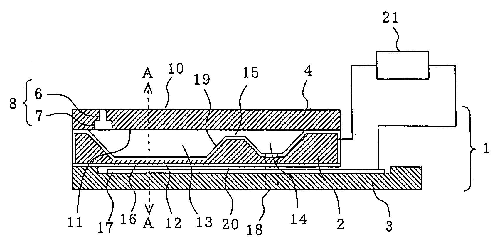
[0064]FIG. 1 is a longitudinal sectional view illustrating a droplet discharge head according to Embodiment 1 of the present invention. In FIG. 1, a drive circuit 21 is schematically illustrated. Furthermore, FIG. 1 illustrates an example of a droplet discharge head including an electrostatic actuator according to the present invention. This droplet discharge head is driven electrostatically and is of face-ejection type.

[0065] The droplet discharge head 1 according to the present Embodiment 1 is a composite mainly of a cavity substrate 2, an electrode substrate 3, and a nozzle substrate 4. The nozzle substrate 4 is formed of silicon and has a nozzle 8, which includes a first nozzle opening 6, for example, of a cylindrical shape and a second nozzle opening 7, for example, of a cylindrical shape, which communicates with the first nozzle opening 6 and is larger in diameter than the first nozzle opening 6. The first nozzle 6 is formed to open a droplet discharge surface 10 (a surface o...

embodiment 2

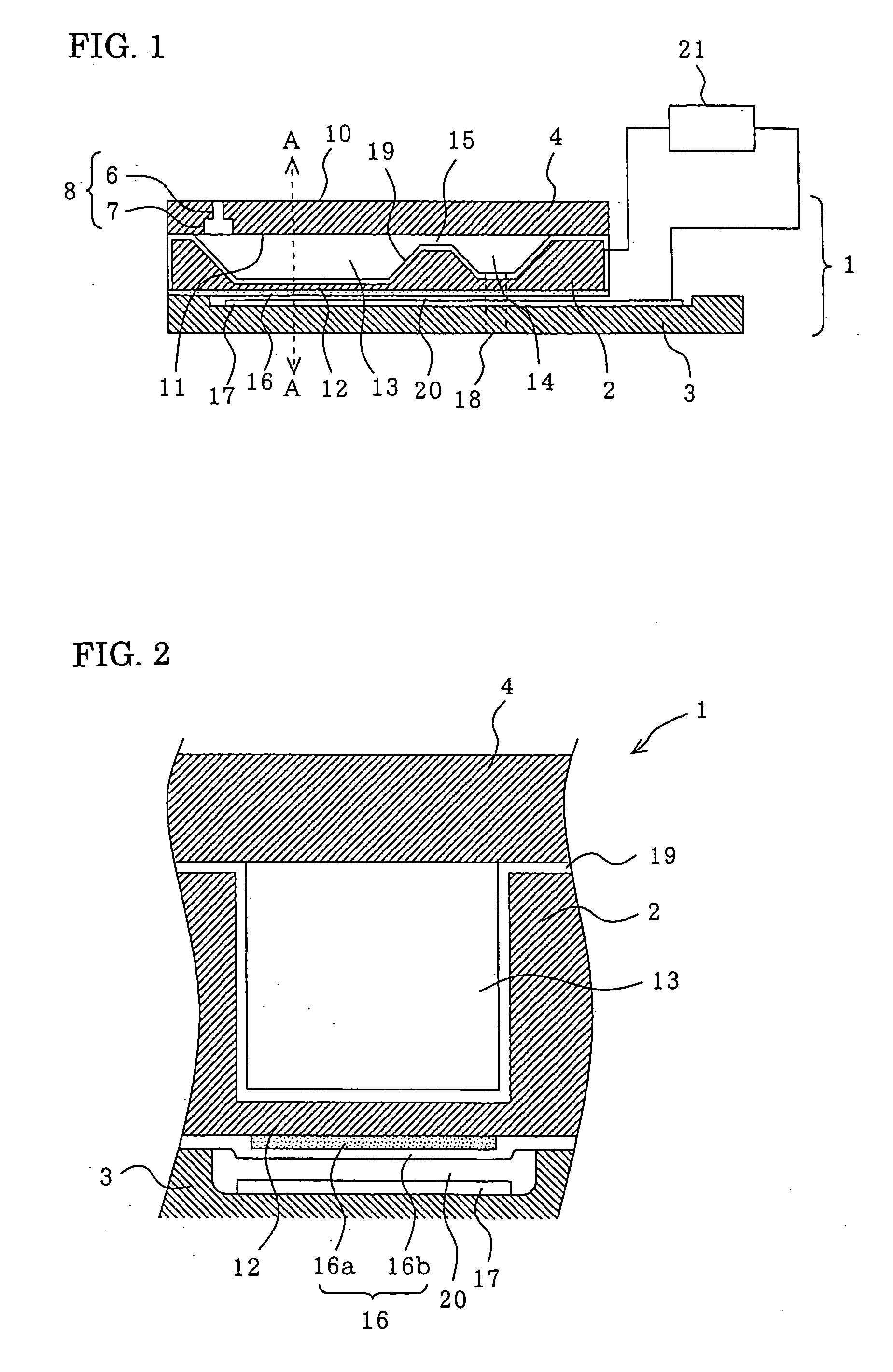
[0100]FIG. 5 is a sectional view illustrating a droplet discharge head according to Embodiment 2 of the present invention. FIG. 5 illustrates a cross section taken along line A-A of FIG. 1, as in FIG. 2. A droplet discharge head 1 according to the present Embodiment 2 is the same as the droplet discharge head 1 in Embodiment 1, except that the silicon oxide film 16b has an opening 25. The same reference numerals used in Embodiments 1 and 2 refer to the same elements.

[0101] In the droplet discharge head 1 according to the present Embodiment 2, the opening 25 in the silicon oxide film 16b is disposed opposite to the counter electrode 17. The dielectric film 16a is disposed in the opening 25. Thus, the dielectric film 16a is exposed to the counter electrodes 17. In this portion where the dielectric film 16a is exposed, the pressure generated at the diaphragm 12 is greater than that in the insulating film having a two-layer structure (see Equations 2 and 3).

[0102] The droplet discharg...

embodiment 3

[0105]FIG. 6 is a sectional view illustrating a droplet discharge head according to Embodiment 3 of the present invention. FIG. 6 illustrates a cross section taken along line A-A of FIG. 1, as in FIG. 2. A droplet discharge head 1 according to the present Embodiment 3 is the same as the droplet discharge head 1 in Embodiment 1, except that the dielectric film 16a is closer to the counter electrode 17 than the silicon oxide film 16b is. The same reference numerals used in Embodiments 1 and 3 refer to the same elements.

[0106] In the droplet discharge head 1 according to the present Embodiment 2, the dielectric film 16a is closer to the counter electrode 17 than the silicon oxide film 16b is and is sectioned opposite to the counter electrode 17. Furthermore, the silicon oxide film 16b is formed on the entire surface of the cavity substrate 2 to which the electrode substrate 3 is bonded.

[0107] The droplet discharge head 1 according to the present embodiment 3 may be manufactured by fo...


PUM


Abstract

To provide an electrostatic actuator that generates high pressure under a given voltage and includes an insulating film exhibiting excellent insulation resistance, a droplet discharge head that includes the electrostatic actuator and a method for manufacturing the droplet discharge head, a droplet discharge apparatus that includes the droplet discharge head and has excellent printing performance, and a device that includes the electrostatic actuator and has excellent driving performance. A diaphragm 12, a counter electrode 17 opposite to the diaphragm 12 with a gap interposed therebetween, and an insulating film 16 on a surface of the diaphragm 12 opposite to the counter electrode 17 are included. The insulating film 16 includes at least a dielectric film 16a formed of a substance having a higher relative dielectric constant than silicon oxide.

Description

[0001] The entire disclosure of Japanese Patent Application No. 2004-361001 filed Dec. 14, 2004, Japanese Patent Application No. 2005-052596 filed Feb. 28, 2005, Japanese Patent Application No. 2005-273797 filed Sep. 21, 2005, are expressly incorporated by references herein. TECHNICAL FIELD [0002] The present invention relates to an electrostatic actuator, a droplet discharge head and a method for manufacturing the droplet discharge head, a droplet discharge apparatus, and a device, and more specifically, it relates to an electrostatic actuator that generates high pressure and has reliable insulation characteristics, a droplet discharge head including the electrostatic actuator and a method for manufacturing the droplet discharge head, a droplet discharge apparatus including the droplet discharge head, and a device including the electrostatic actuator. BACKGROUND ART [0003] An ink-jet printer has many advantages, such as high-speed printing capability, very low noise during printing...

Claims


Application Information

Patent Timeline
Patent Type & Authority Applications(United States)
IPC IPC(8): B41J2/04
CPCB41J2/14274B41J2/1612B41J2/1623B41J2/1626B41J2/14072B41J2/3351B41J2002/062
Inventor FUJII, MASAHIROARAKAWA, KATSUJI
Owner SEIKO EPSON CORP
Why Eureka
Try Eureka