Light beam deflector

a light beam and deflector technology, applied in the field of excellent light beam deflectors, can solve the problems of more complex components, more light beams, and more aberration, and achieve the effects of simple structure, reduced vibration, and reduced cos

Inactive Publication Date: 2006-06-15
FUJIFILM HLDG CORP +1
View PDF5 Cites 3 Cited by
  • Summary
  • Abstract
  • Description
  • Claims
  • Application Information

AI Technical Summary

Benefits of technology

[0013] In light of the problem described above, an object of the present invention is to provide a new light beam deflector which realizes an astigmatic difference correction component with simple structure at a prism member including a reflective surface, for reflecting a condensed light beam in order to perform deflective scanning, and which can be fabricated at low cost.
[0015] According to the structure as described above, an inclined surface is integrally formed at the cubic prism, and the correction inclination angle and the inclination direction of the inclined surface compensate so as to reduce astigmatism that arises at the reflection surface. Thus, a light beam that has passed through the cubic prism is narrowly constricted and excellently focused to a beam spot. Thus, an image can be exposed with high precision without experiencing adverse effects from astigmatism, and it is possible to form a precise image and maintain stable image quality during recording exposure.
[0020] According to the structures described above, the cubic prism can be formed with rotational symmetry about the axis of rotation. Hence, it is possible to suppress vibrations when the cubic prism is rotated at high speed.
[0021] According to the present invention, a light beam deflector is employed which realizes an astigmatic difference correction component with simple structure integrally with a prism member that includes a condensed light beam reflection surface for performing deflective scanning. As a result, there is an effect in that fabrication at low cost is possible.

Problems solved by technology

Thus, the inclined mirror is deformed by centrifugal force, and an aberration arises in the light beam.
However, with an astigmatic difference correction component of a conventional light beam deflector that is structured thus, because of the structure in which the inclined mirror to be rotated at high speed is disposed inside the tubular casing and the optically flat glass plate is mounted at the opening portion of the tubular casing such that the angle thereof is adjustable, there are problems in that components are more numerous and more complex, and the light beam deflector is more expensive.
Moreover, because weight of the light deflection section is heavier, there is a problem in that, given the same motor, there is a limitation on speeds of rotation at which it is possible to rotate.

Method used


Image

  • Light beam deflector
  • Light beam deflector
  • Light beam deflector

Examples


Embodiment Construction

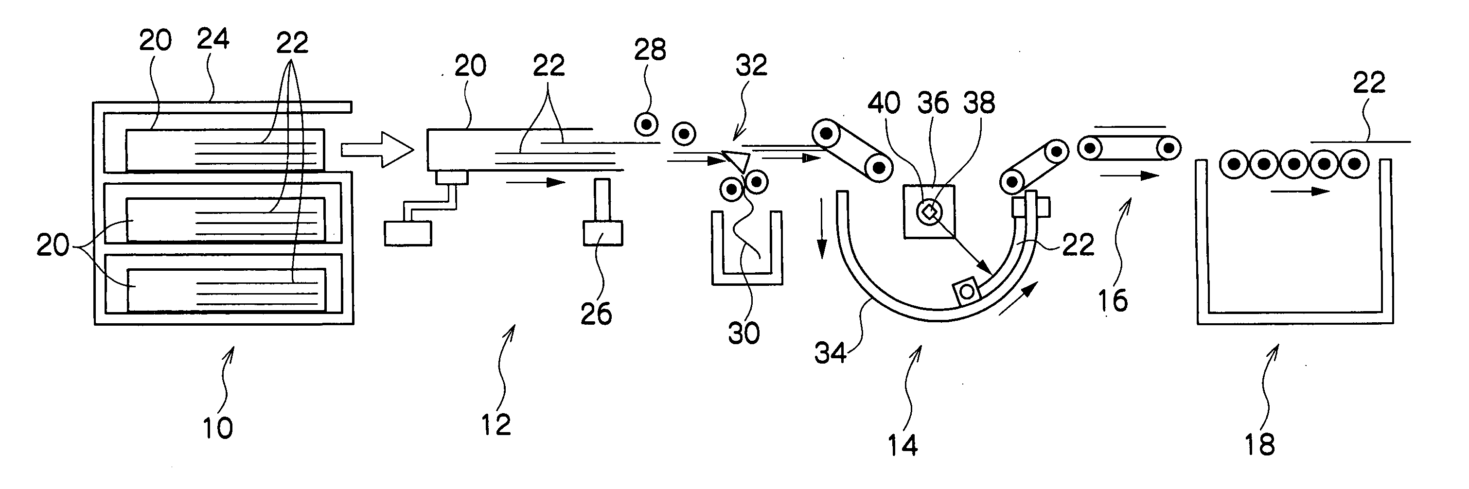
[0046] An embodiment relating to a light beam deflector of the present invention is described with FIGS. 1 to 10. The light beam deflector relating to the present embodiment is suitable for employment in a CTP (computer-to-plate) system in which a photosensitive planographic printing plate (PS plate) for offset printing serves as a recording medium, laser exposure processing is performed on the basis of digital data from a computer or the like, development processing at an automatic developer converts a latent image formed on the photosensitive planographic printing plate to a visible image, and a direct printing plate is produced.

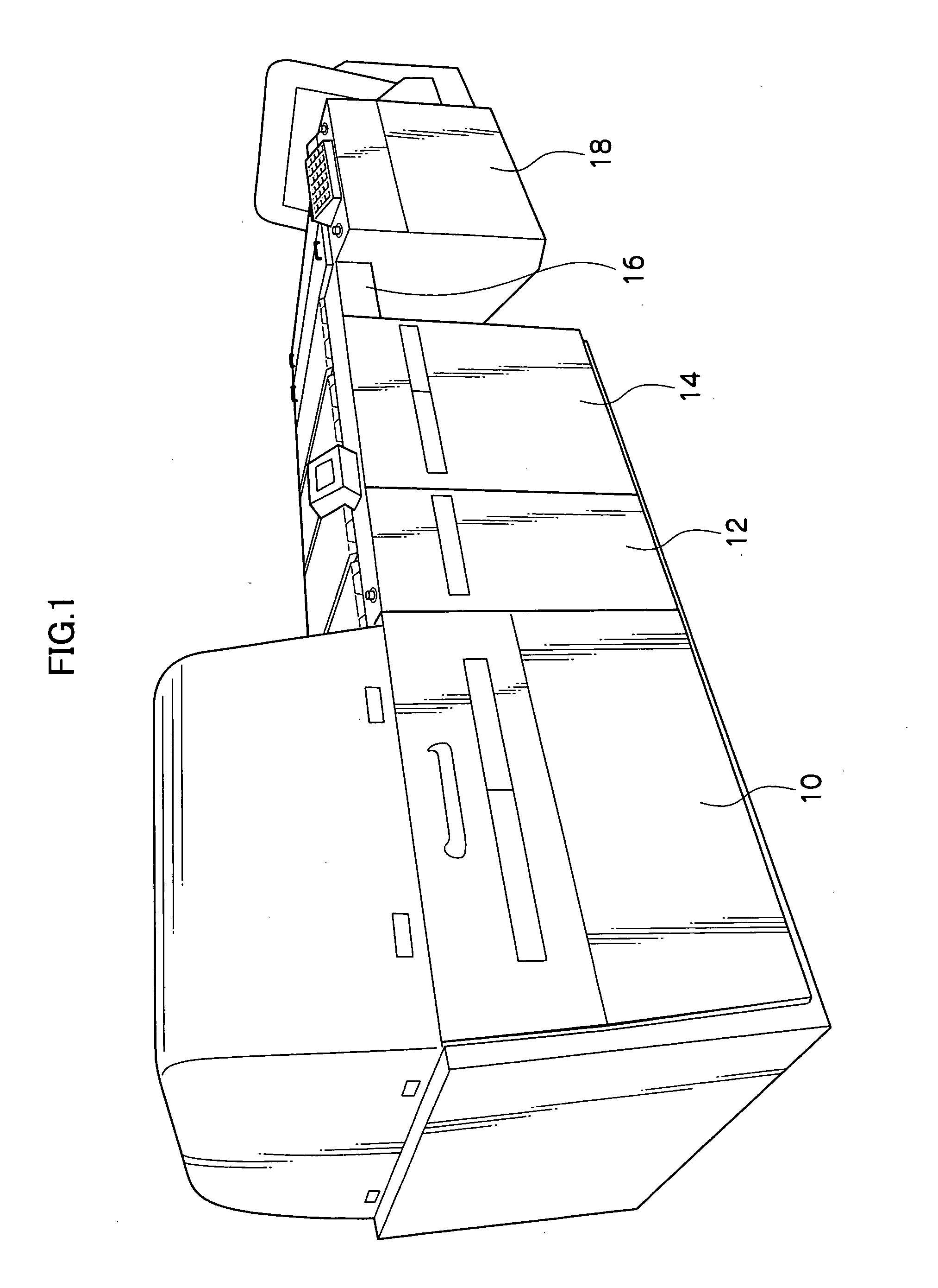
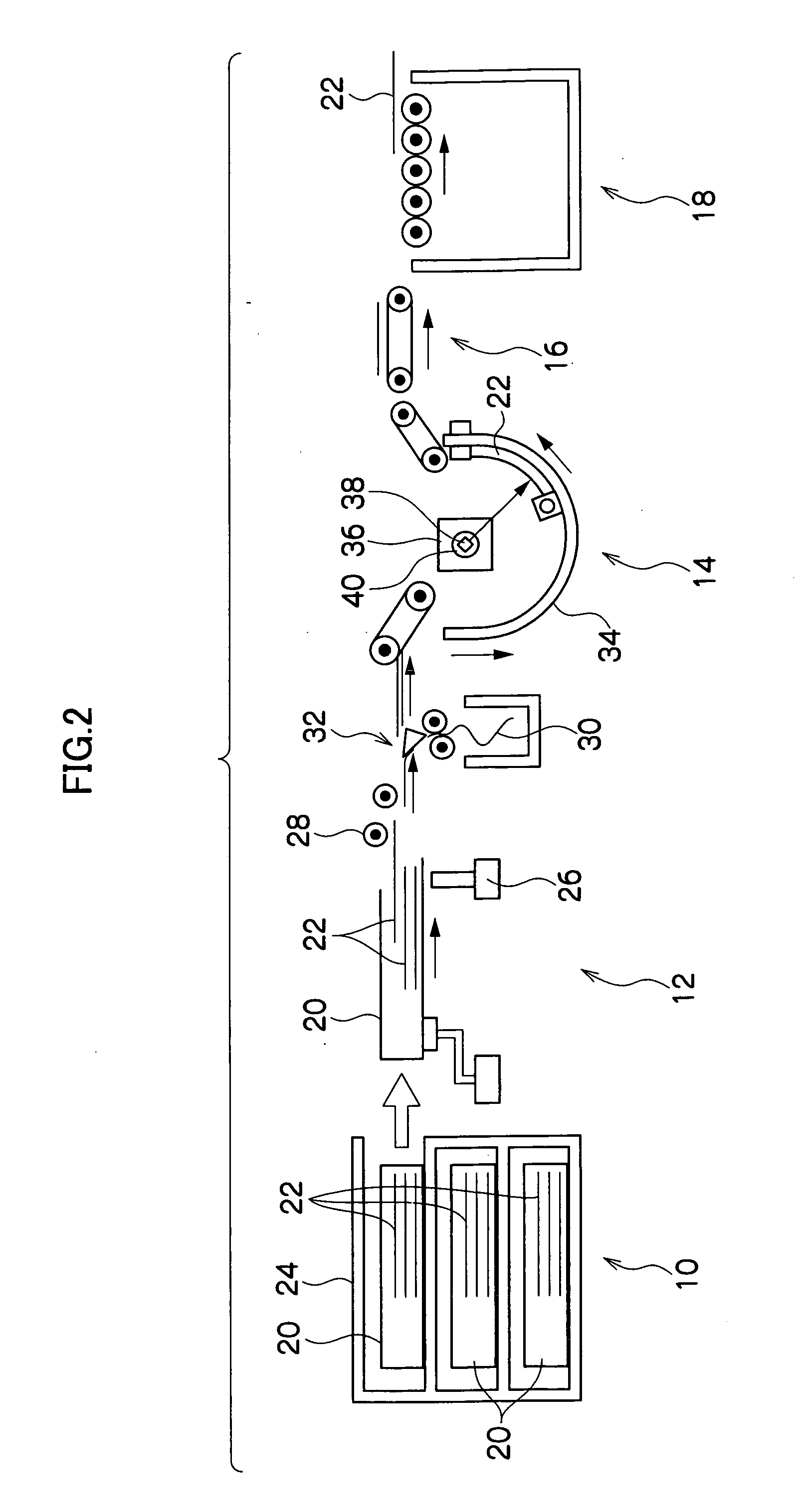
[0047]FIGS. 1 and 2 show, in relation to the present embodiment, general structure of a CTP (computer-to-plate) system which is equipped with an inner drum exposure apparatus including a light beam deflector which realizes an astigmatic difference correction component.

[0048] This CTP system is equipped with an automatic feeding apparatus 10 with printing...


PUM

PropertyMeasurementUnit
angleaaaaaaaaaa
reflection angleaaaaaaaaaa
inclination angleaaaaaaaaaa

Abstract

A light beam deflector for recording an image at a recording medium, at which a light beam modulated in accordance with image information passes through an incidence face of a cubic prism which is driven to rotate, the light beam deflector reflecting the light beam at a reflection surface, emitting the light beam through an emission face, and deflecting and scanning the light beam. An astigmatic difference correction surface is structured at at least one of the light beam incidence face and emission face of the cubic prism. The astigmatic difference correction surface is set with an inclination angle and inclination direction that are suitable for correcting astigmatism which arises due to the light beam passing through the incidence face, being reflected at the reflection surface and passing through the emission face.

Description

CROSS-REFERENCE TO RELATED APPLICATION [0001] This application claims priority under 35 USC 119 from Japanese Patent Application No. 2004-358917, the disclosure of which is incorporated by reference herein. BACKGROUND OF THE INVENTION [0002] 1. Field of the Invention [0003] The present invention relates to an excellent light beam deflector, which is employed at an inner drum exposure apparatus (an inner face scanning-type light beam-scanning exposure apparatus) which scans a photosensitive surface disposed at an inner face of a cylindrical drum with a laser beam scanning optical system to perform exposure processing, or the like, and which corrects for astigmatism. [0004] 2. Description of the Related Art [0005] For offset printing, photosensitive planographic printing plates (PS plates) are commonly employed. In the field of printing on these plates, CTP (computer-to-plate) systems have been realized which perform laser exposure processing based on digital data from a computer or t...

Claims


Application Information

Patent Timeline
Patent Type & Authority Applications(United States)
IPC IPC(8): G02B26/08B41J2/44G02B26/10G03F1/00G03F7/20H04N1/036H04N1/113
CPCG02B26/108
Inventor MIYAGAWA, ICHIROU
Owner FUJIFILM HLDG CORP
Why Eureka
Try Eureka