[0004] In contrast, the heating and / or cooling
system in accordance with the invention offers the
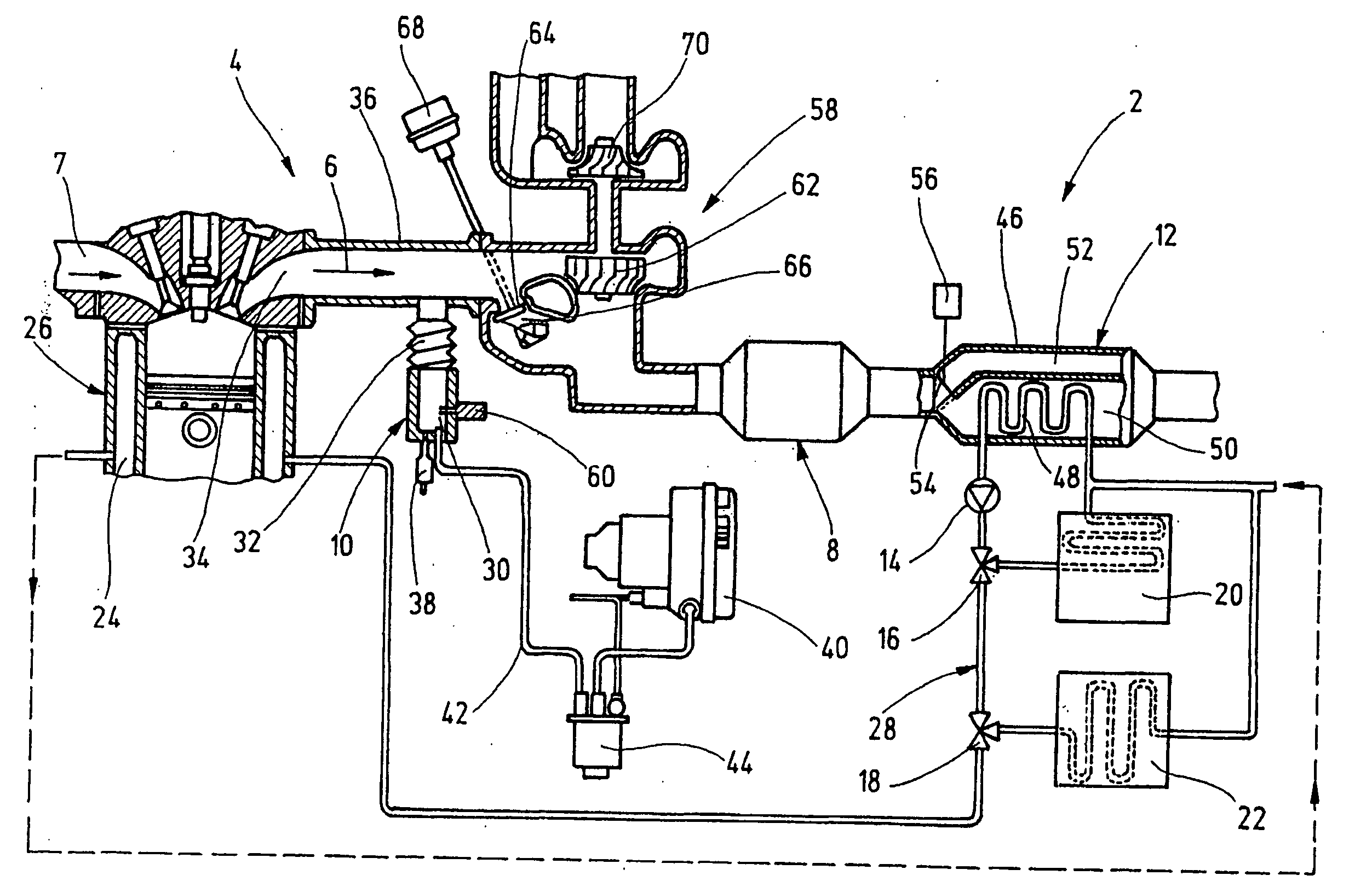
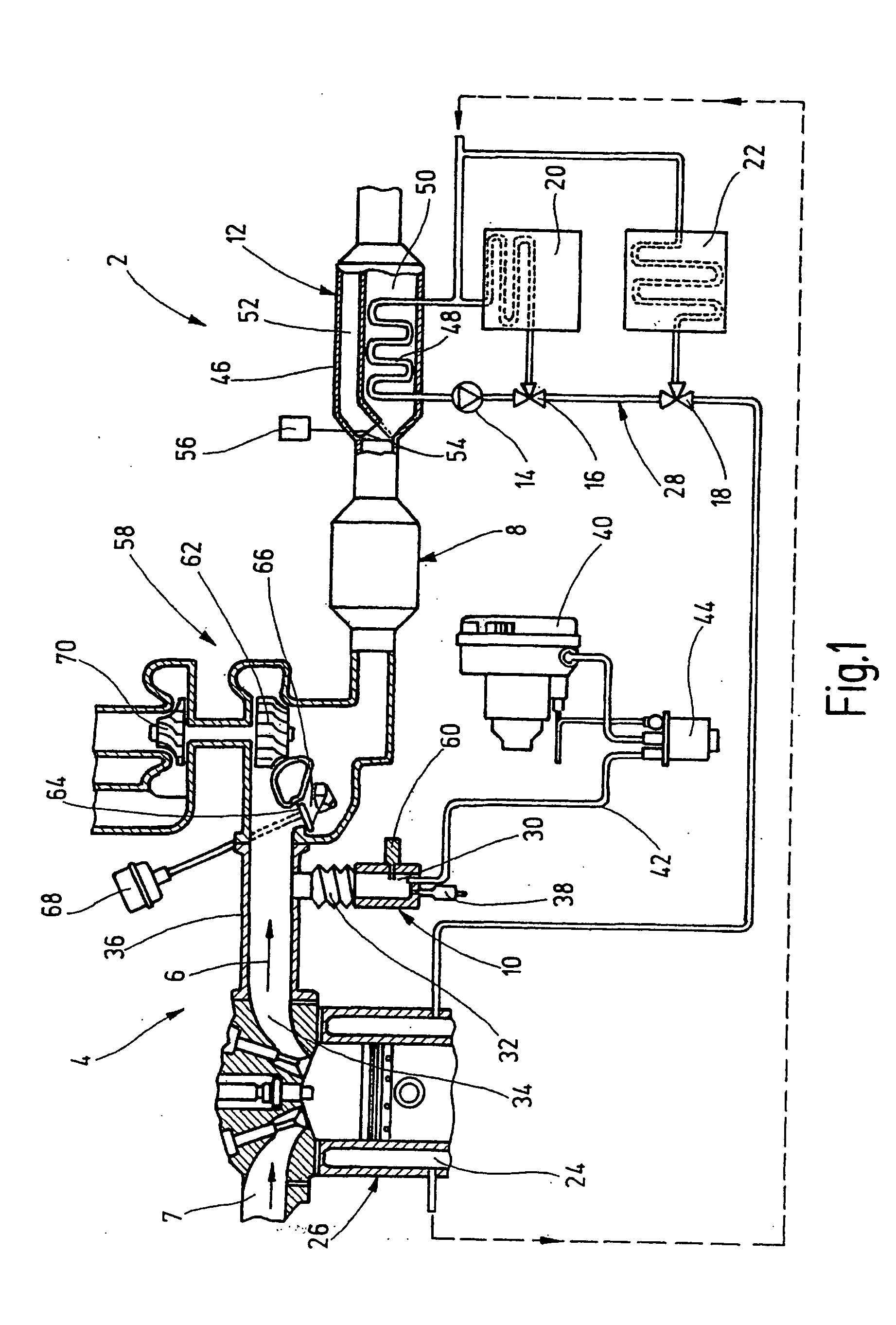
advantage that very quick heating of the catalytic converter is enabled since the combustion gases flowing through the catalytic converter from the burner only cool down a little before reaching the catalytic converter. The invention is based on the idea of using the hot combustion gases from the burner first for heating the catalytic converter in order to bring it as quickly as possible to its high
operating temperature that is required for exhaust gas purification, and then to use said gases to heat the combustion engine and / or to heat the vehicle. Since the heating capacity of the catalytic converter is relatively low as compared with that of the combustion engine, noticeably quicker heating of the catalytic converter can be achieved in comparison to the arrangement from the prior art in accordance with DE 100 05 490 A1 without considerably reducing the
heat supply to the combustion engine or to the heating system.
[0005] A preferred embodiment of the invention provides that the heat exchanger for heating the combustion engine be attached to said combustion engine's coolant circuit so that the coolant of the combustion engine after heating in the heat exchanger can be supplied directly to the coolant ducts or coolant spaces of the combustion engine in order to increase its temperature for reducing the
pollutant emissions and fuel consumption before a
cold start.
[0006] According to another preferred embodiment of the invention, the heat exchanger also forms a part of the auxiliary heater of the motor vehicle and for this purpose is expediently attached to a heating circuit of a heating system of the motor vehicle so that the heat of the hot combustion gases of the burner at low ambient temperatures before starting the vehicle, can be utilized to improve
driving safety or increase comfort, in that windows, seats and / or the passenger compartment of the motor vehicle are heated with the auxiliary heater.
[0007] In the case of motor vehicles with
hybrid propulsion, in which when operating an
electric machine as driving propulsion, the quantity of heat adequate to heat the motor vehicle is not generated, the heat exchanger attached to the heating circuit can also form part of an additional heater, in which the required quantity of heat is generated by starting the burner during operation of the
electric machine. If the burner is used at low ambient temperatures to generate heat during essentially the entire operating duration of the
electric machine, the arrangement of the heat exchanger behind the catalytic converter also has the
advantage that the catalytic converter is kept constantly at its optimal
operating temperature so that exhaust gas limit values cannot be exceeded during the subsequent starting of the combustion engine. If no additional heating is required at high ambient temperatures, the burner can be activated expediently briefly before starting the combustion engine in order to heat up the catalytic converter beforehand.
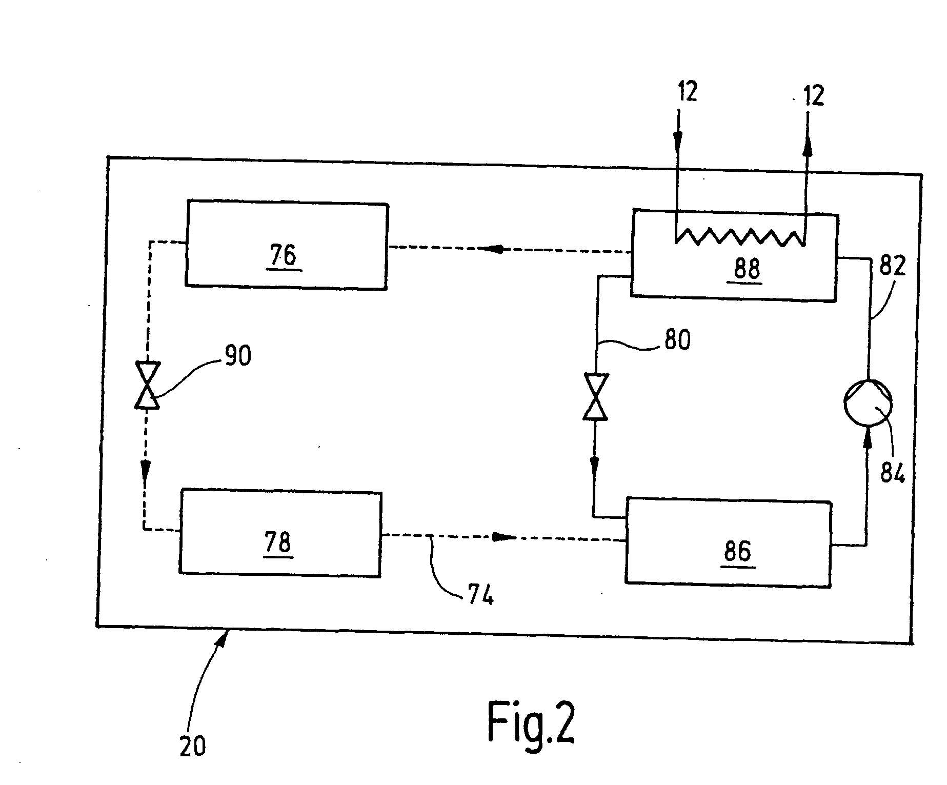
[0008] Another preferred embodiment of the invention provides that the heat exchanger be attached to an absorption type refrigerating
machine of an air conditioner of the motor vehicle. Firstly, this makes independent
air conditioning of the vehicle possible at high ambient temperatures by starting the burner without a danger of draining the vehicle battery. Since hot exhaust gases from the combustion engine flow through the heat exchanger when the combustion engine is being operated, this measure also makes
air conditioning the vehicle possible during vehicle operation without the higher fuel consumption or performance losses in the combustion engine that are caused by a conventional air conditioner. Secondly, the absorption type refrigerating
machine can alternatively or additionally be used to cool an
exhaust gas recirculation system of the combustion engine and / or to cool the charge air of a charge air cooler that is standard in turbocharged engines.
[0009] According to another preferred embodiment of the invention, the energy of the hot combustion gases of the burner in motor vehicles with turbochargers is used to propel an exhaust gas
turbine of the
turbocharger in order to avoid the so-called “turbo
lag” in the combustion engine's lower rmp range. For this purpose, the exhaust gas
turbine of the
turbocharger is expediently arranged before the catalytic converter in the exhaust gas path of the combustion engine so that the hot combustion gases from the burner can be directed as needed throughout the exhaust gas
turbine. In order to prevent the combustion gases from being directed through the exhaust gas turbine during a
cold start, a bypass line is expediently provided through which the combustion gases can bypass the exhaust gas turbine.

