Heat dissipating assembly for a heat element

a technology of heat dissipation assembly and heat element, which is applied in the direction of basic electric elements, electrical apparatus construction details, lighting and heating apparatus, etc., can solve the problems of short lifespan, decrease in brightness, and efficiency of light source temperature reduction, and achieves high efficiency of electric energy transformation, increase the brightness and durability of led chips, and reduce the effect of temperatur

Inactive Publication Date: 2006-06-22
CLEVAGE ENTERPRISE
View PDF10 Cites 9 Cited by
  • Summary
  • Abstract
  • Description
  • Claims
  • Application Information

AI Technical Summary

Benefits of technology

[0005] The primary object of the present invention is to provide a heat dissipating assembly for a heat element. In the heat dissipating assembly, a light source is set on the board. By quickly conducting the heat of a light source to a heat dissipating sheet through a heat conductive layer, the temperature of the light source is decreased efficiently and the transformation efficacy of electric energy is highly improved, which increases the brightness and durability of LED.

Problems solved by technology

Because electric energy cannot transform into light energy efficiently when current passes through LED chips, there is always a temperature increase in LED chips which results in the decrease of brightness and durability of LED chips.
Accordingly, there is a need of dissipating design for products with LED as light source which otherwise will be bothered by problems like decrease in brightness and short lifespan.
Although conventional MCPCB can conduct heat, there is no medium for drawing out heat source quickly to a heat dissipating sheet.
Due to the lack of efficient heat conducting means, LED fails to be used in a high density way and high power application.

Method used


Image

  • Heat dissipating assembly for a heat element
  • Heat dissipating assembly for a heat element
  • Heat dissipating assembly for a heat element

Examples


Embodiment Construction

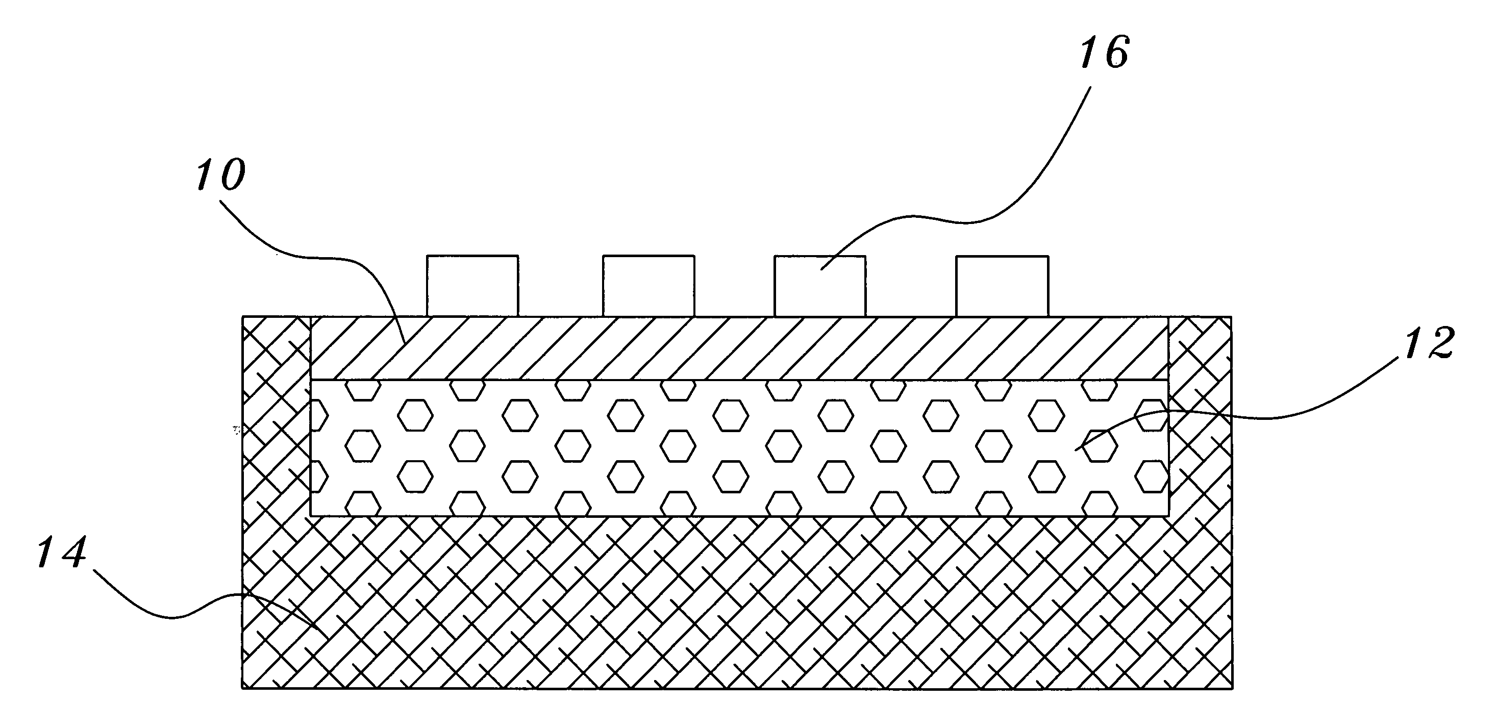
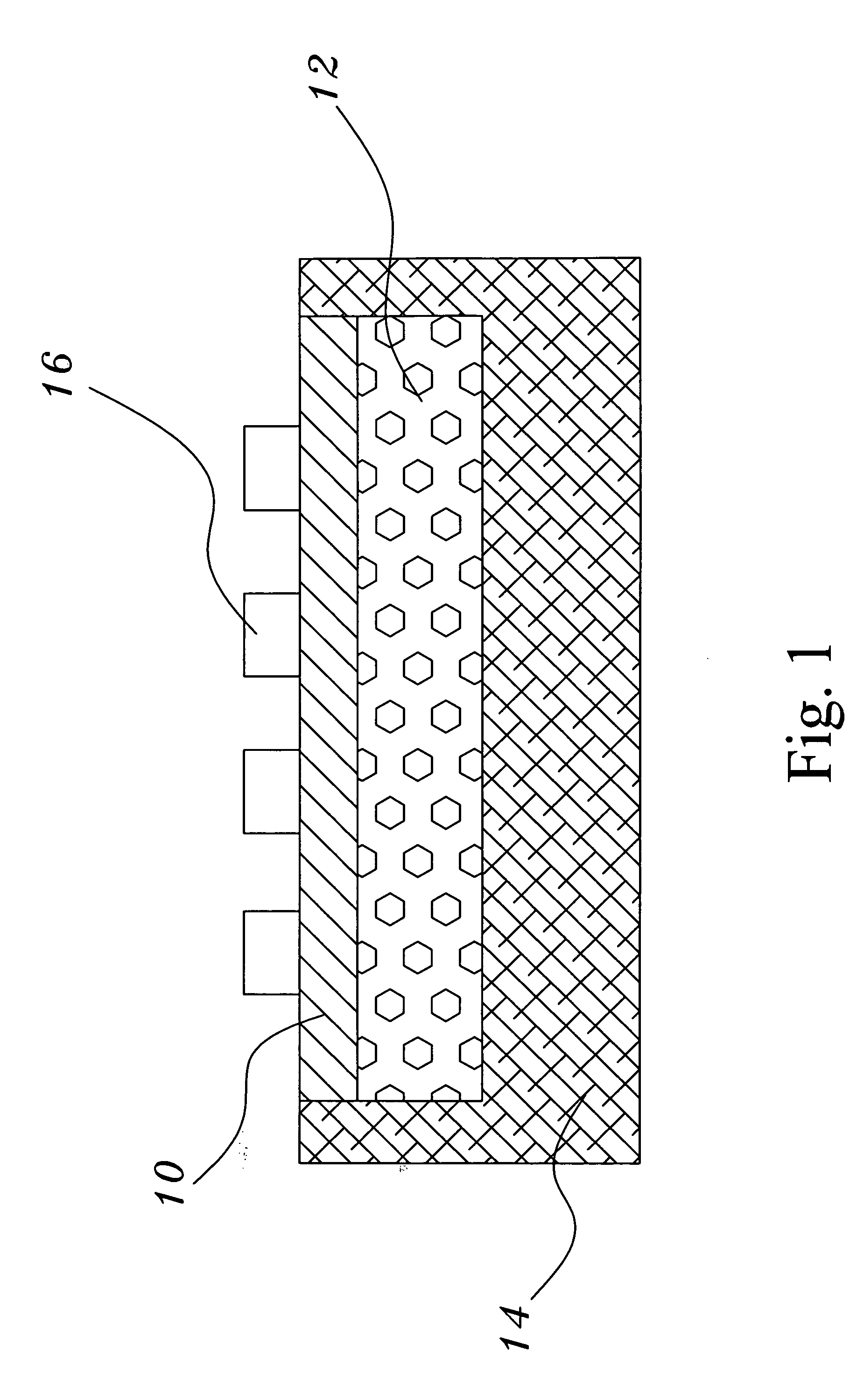
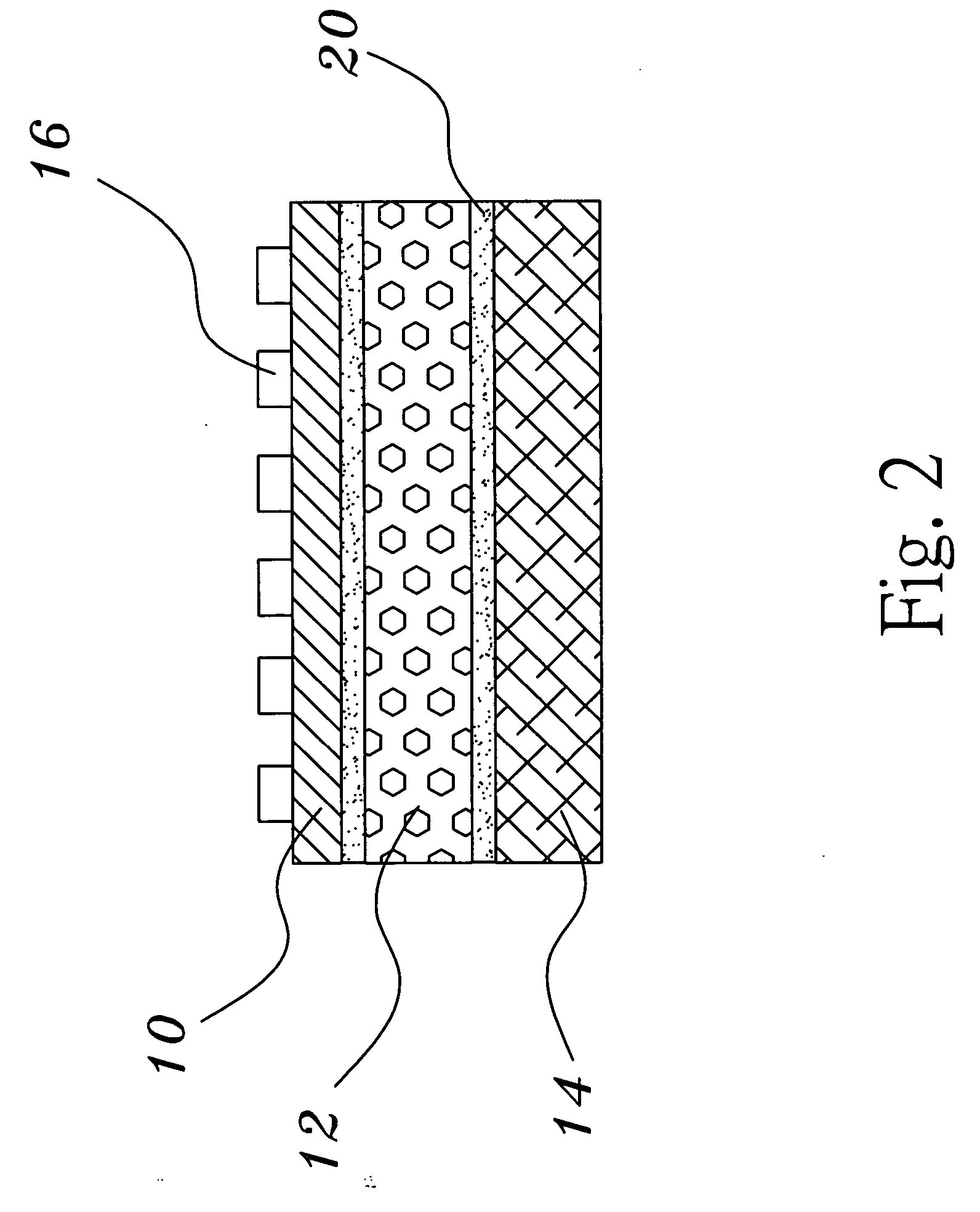
[0008] The present invention relates to a heat dissipating assembly for a heat element which as shown in FIG. 1 and FIG. 2. The heat dissipating assembly comprises a board 10, a heat conductive layer 12, a heat dissipating sheet 14 and a heat source 16 which are combined by squeezing bonding or fusing adhesion. Said heat source 16 is light emitting diode (LED) or is made up of heat generating electronic elements. On the board 10 a plurality of heat sources 16 are set and the heat conductive layer 12 is set under the board 10 and above the heat dissipating sheet 14. The material of the heat conductive layer is chosen from graphite or carbon fiber. The material of the board 10 and the heat dissipating sheet are selected from the group consisting of ceramic, copper, aluminum and aluminum-magnesium alloy. As shown in FIG. 1, the heat dissipating assembly for a heat element is form by a tight squeeze bonding of the board 10, the heat conductive layer 12 and the heat dissipating sheet 14....


PUM


Abstract

The present invention provides a heat dissipating assembly for a heat element comprising a board on which at least a heat source, heat conductive layer and a heat dissipating sheet are set. The heat conductive layer is formed between the heat dissipating sheet and the board by squeeze bonding, thermal fusion or ultrasonic fusion. The heat conductive layer is made up of a material possessing the properties of quick heat conduction and compressive flexibility. While the heat conductive layer is adhered by squeeze bonding, thermal fusion or ultrasonic fusion, heat is conducted by its entire surface. The present invention is able to raise the heat dissipating efficacy and draw out the heat from the heat source quickly, therefore, increases the brightness and durability of the light source.

Description

FIELD OF THE INVENTION [0001] The present invention relates to a heat dissipating assembly, more particularly, to a heat dissipating assembly for a heat element possessing satisfied heat dissipating efficacy for the use of light source under high power. DESCRIPTION OF RELATED ART [0002] The application of light emitting diode (LED) is very broad at the present time. By the improvement of the brightness of LED, it can now be used in various illumination applications such like headlights of vehicle peripherals, light sources for reading, big-sized back lights and the back lights of LED TV. [0003] Because electric energy cannot transform into light energy efficiently when current passes through LED chips, there is always a temperature increase in LED chips which results in the decrease of brightness and durability of LED chips. Accordingly, there is a need of dissipating design for products with LED as light source which otherwise will be bothered by problems like decrease in brightnes...

Claims


Application Information

Patent Timeline
Patent Type & Authority Applications(United States)
IPC IPC(8): H05K7/20H01L23/34H01L23/373H01L33/64
CPCH01L23/3735H01L33/641H05K7/205H01L2924/0002H01L2924/00
Inventor HSU, CHIH-MINGLIN, CHUNG-CHENGLEE, CHIN-TING
Owner CLEVAGE ENTERPRISE
Why Eureka
Try Eureka