Transponder assembly for use with parallel optics modules in fiber optic communications systems

a technology of parallel optics and transponder assembly, which is applied in the manufacture of final products, electrical apparatus casings/cabinets/drawers, instruments, etc., can solve the problems of limited capacity of electrical signals carried by copper wiring for carrying digital data, and achieve compact size, small footprint, and efficient and effective

Inactive Publication Date: 2006-06-22
STRATOS INT
View PDF6 Cites 9 Cited by
  • Summary
  • Abstract
  • Description
  • Claims
  • Application Information

AI Technical Summary

Benefits of technology

[0010] The transponder assembly includes a parallel optics transmitter module and a parallel optics receiver module having pluggable edge connectors. The assembly also includes a circuit board mounting a Serializer / Deserializer (SerDes) chip and the pin-array type electrical connector. A flexible printed circuit or Flex circuit is used to flexibly connect the circuit board to a connector board mounting a pair of connection jacks which interconnect with the edge connectors of the parallel optics modules. The Flex circuit allows the alignment of the circuit board and parallel optics modules to be adjusted for providing an assembly having minimum depth dimensions. The SerDes chip and pin-array connector are mounted directly across from one another on opposite surfaces of the circuit board using ball grid arrays having areas in which their attachments are positioned in between one another in the overlapping areas. The solder pads associated with the vias having the same connection functionality are interconnected by surface traces and redundant vias are eliminated in order to allow adequate pathways for circuit traces to within the circuit board structure to extend through the overlapping areas of the ball grid array attachments. Placement of the pin-array connector and the SerDes chip across from one another on the circuit board allows for an assembly having minimum lateral dimensions.
[0012] It is another object of the present invention to provide a transponder assembly which utilizes separate parallel optic transmitter and receiver modules in an assembly having a compact size and minimum footprint.
[0013] It is a further object of the present invention to provide for the internal components of a parallel optics transponder assembly to be flexibly interconnected whereby a compact size can be achieved.
[0015] It is a yet further object to provide an efficient and effective parallel optics transponder assembly featuring a compact size and small footprint.

Problems solved by technology

However, electrical signals carried by copper wiring have a limited capacity for carrying digital data.
However, for most applications these transponder assemblies must be compact and should utilize only the smallest possible footprint on the circuit boards within the electronic computing or communications devices with which the fiber optic network is interfacing.

Method used


Image

  • Transponder assembly for use with parallel optics modules in fiber optic communications systems
  • Transponder assembly for use with parallel optics modules in fiber optic communications systems
  • Transponder assembly for use with parallel optics modules in fiber optic communications systems

Examples


Embodiment Construction

[0028] The present invention will now be described in detail with reference to preferred embodiments as illustrated in the accompanying drawings. In the following description, numerous specific details are set forth in order to provide a thorough understanding of the present invention. However, it should be apparent to one skilled in the art that the present invention may be practiced without some or all of these specific details. In other instances, it should be appreciated that well-known process steps have not been described in detail in order to not obscure the present invention.

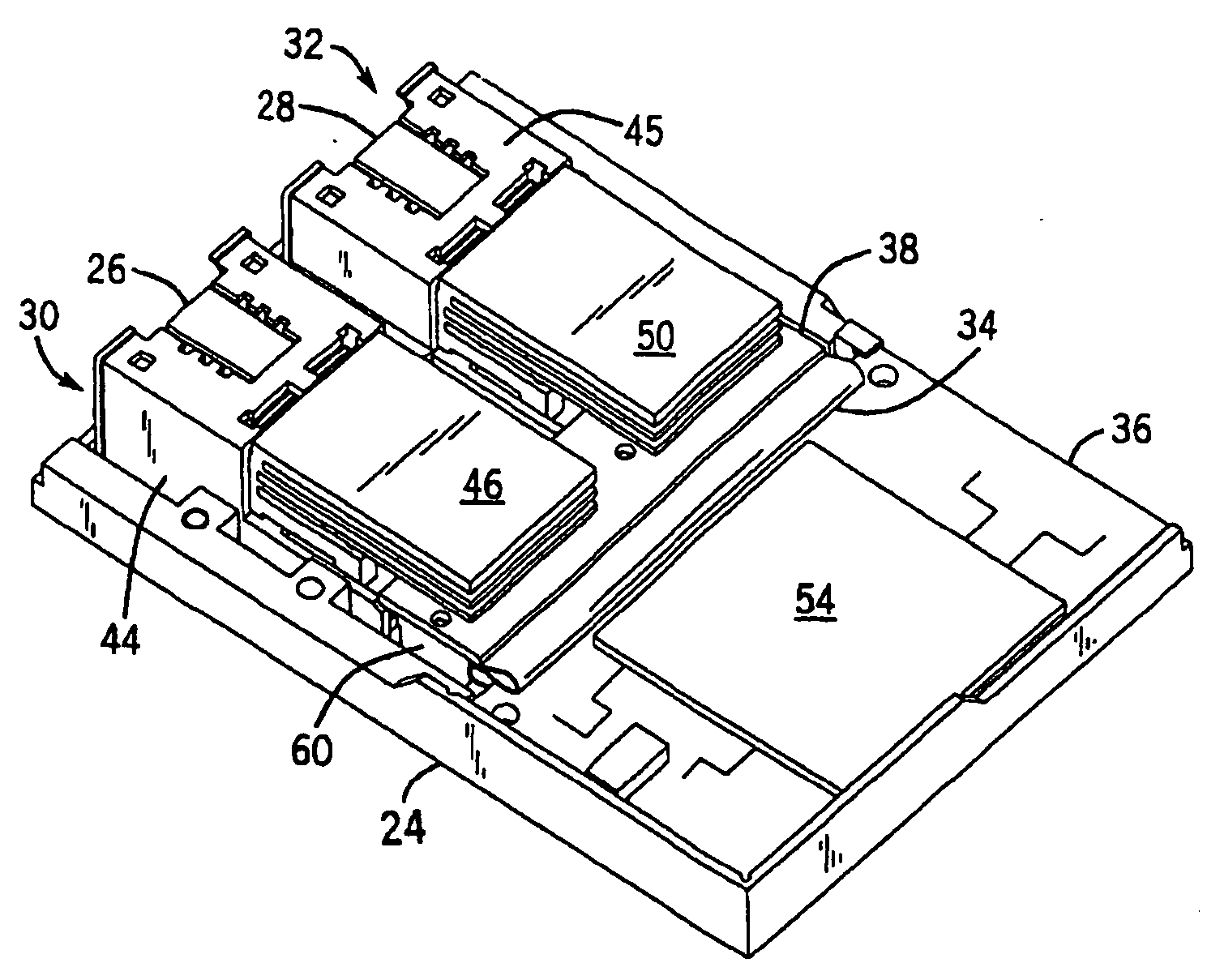
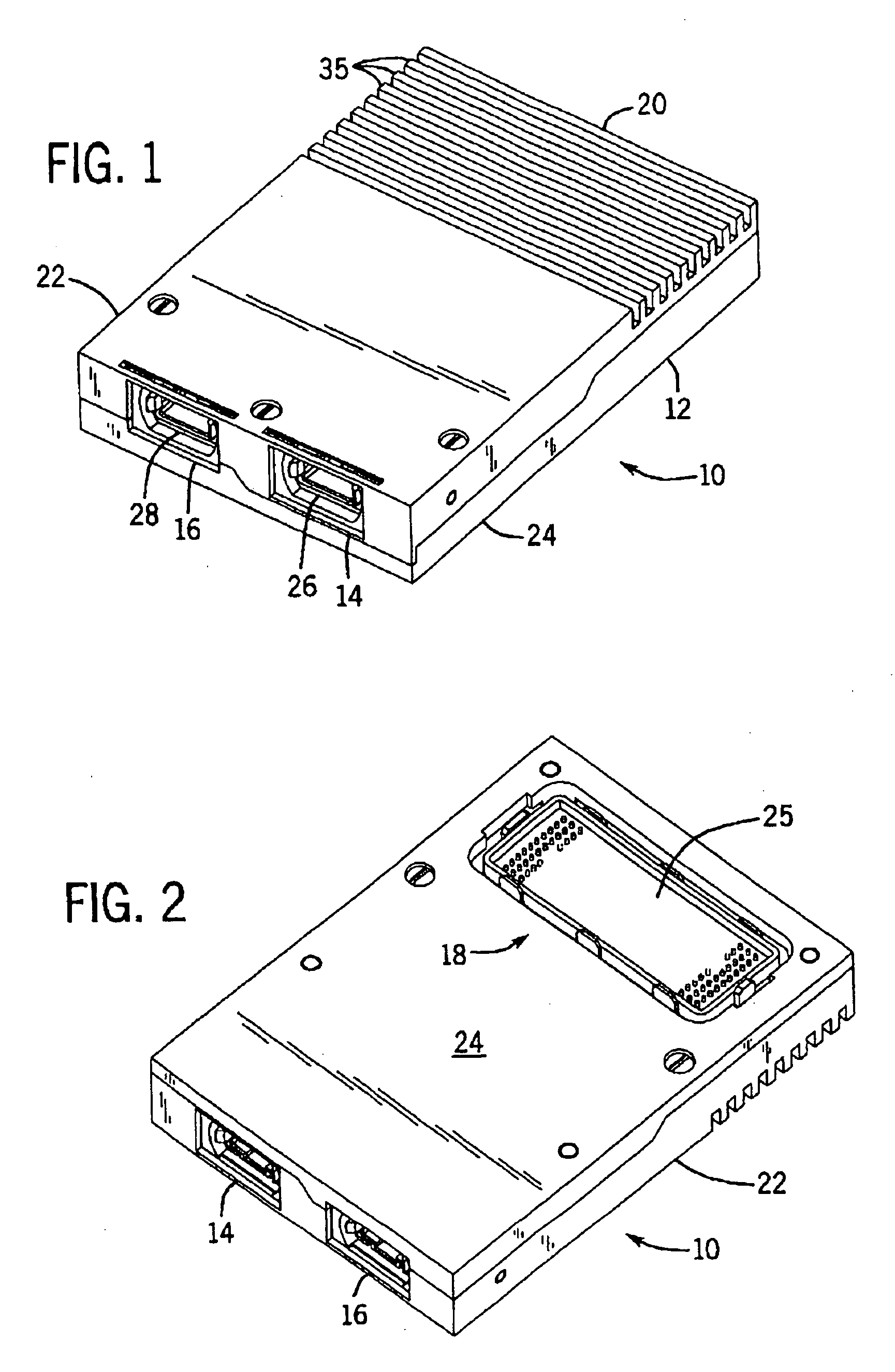
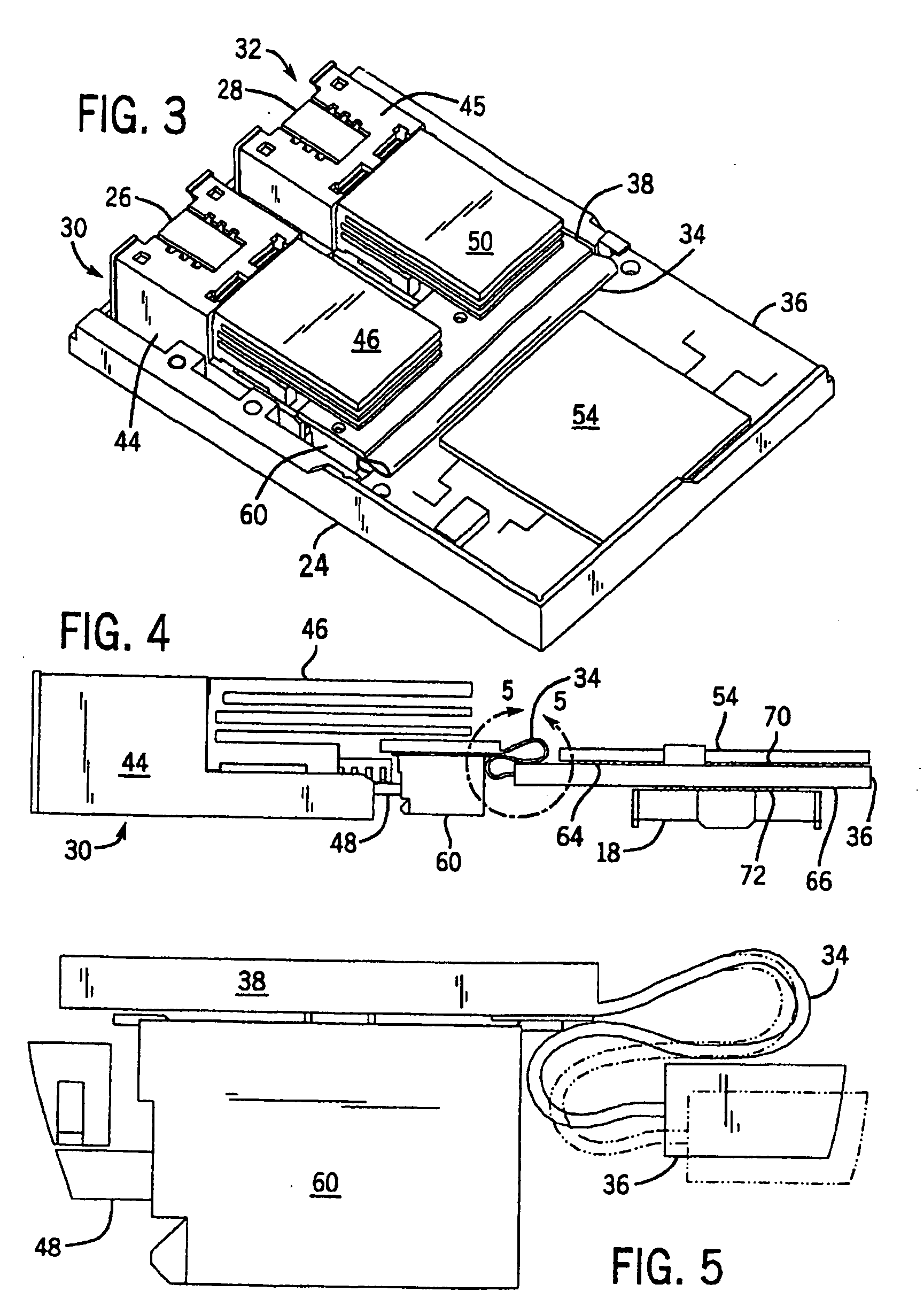
[0029] Referring now to FIGS. 1 and 2, a transponder assembly 10 is shown as including a two-piece housing 12, two communication ports 14 and 16, a pin-array type electrical connector 18 and a heat sink 20. The pin-array connector 18 is preferably a 300-pin MEG Array™ electrical connector (which may be purchased from FCI USA, AREVA Group, having US offices at 825 Old Trail Road in Etters, Pa., 17319). T...


PUM


Abstract

A transponder assembly for use with fiber optic digital communication cables having multiple parallel optic fiber elements. The transponder assembly features a transmitter port and receiver port for connection with separate parallel optic cables for separately transmitting and receiving data and an electrical connector for connecting with computer or communication systems. The transponder assembly includes a parallel optic transmitter module and a parallel optic receiver module having pluggable edge connectors. The assembly also includes a circuit board on which a semiconductor chip useful for signal processing and the electrical connector are mounted. A flex circuit is used in connecting the circuit board to the parallel optic modules. The semiconductor chip and electrical connector are mounted directly across from one another on opposite surfaces of the circuit board.

Description

[0001] This is a division of application Ser. No. 10 / 237,823 filed Sep. 6, 2002, which is hereby incorporated herein by reference.BACKGROUND OF THE INVENTION [0002] 1. Field of the Invention [0003] The present invention relates to the use of optoelectronic components in fiber optic digital communication networks and, more particularly, to transponder assemblies which transmit and receive optical signals over fiber optic ribbon cables having multiple fiber optic elements. [0004] 2. Discussion of the Background [0005] The majority of computer and communication networks in use today rely on copper wiring to transmit data between network nodes. However, electrical signals carried by copper wiring have a limited capacity for carrying digital data. [0006] Many computer and communication networks, including large parts of the Internet, are now being built using fiber optic cabling that can be used to transmit much greater amounts of data. With fiber optic elements, data is transmitted usin...

Claims


Application Information

Patent Timeline
Patent Type & Authority Applications(United States)
IPC IPC(8): H04B10/00H01R12/16G02B6/42H05K1/11H05K1/14H05K1/18H05K3/42
CPCG02B6/4292H05K1/114H05K1/148H05K1/181H05K3/429H05K2201/09227H05K2201/10189H05K2201/10545H05K2201/10734Y02P70/50
Inventor WANG, WILLIAMCHENG, HENGJULO, WEIZEN
Owner STRATOS INT
Why Eureka
Try Eureka