Fuel cell system
- Summary
- Abstract
- Description
- Claims
- Application Information
AI Technical Summary
Benefits of technology
Problems solved by technology
Method used
Image

Examples
first embodiment
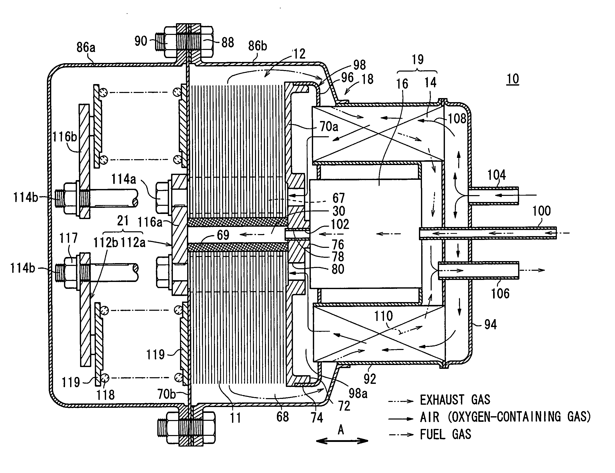
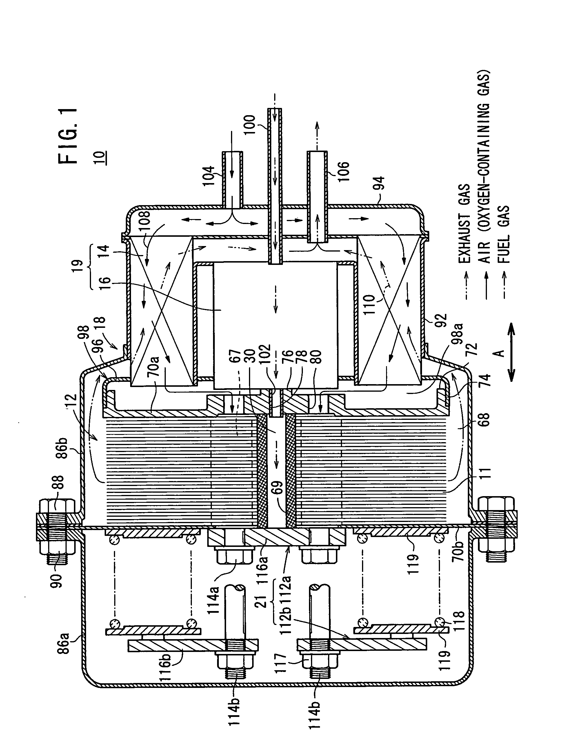
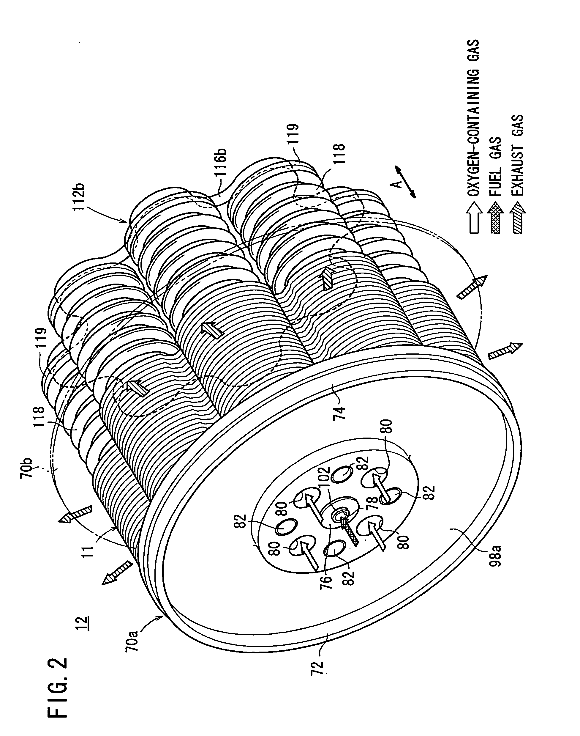
[0038]FIG. 1 is a partial cross sectional view showing a fuel cell system 10 according to the present invention. FIG. 2 is a perspective view schematically showing a fuel cell stack 12 of the fuel cell system 10. The fuel cell stack 12 is formed by stacking a plurality of fuel cells 11 in a direction indicated by an arrow A.
[0039] The fuel cell system 10 is used in various applications, including stationary and mobile applications. For example, the fuel cell system 10 is mounted on a vehicle. As shown in FIG. 1, the fuel cell system 10 includes the fuel cell stack 12, a heat exchanger 14, a reformer 16, and a casing 18. The heat exchanger 14 heats the oxygen-containing gas before it is supplied to the fuel cell stack 12. The reformer 16 reforms a fuel to produce a fuel gas. The fuel cell stack 12, the heat exchanger 14, and the reformer 16 are disposed in the casing 18.
[0040] In the casing 18, a fluid unit 19 including at least the heat exchanger 14 and the reformer 16 is disposed ...
second embodiment
[0089] In the second embodiment, the fuel gas flows from the fuel gas supply pipe 100 to the fuel gas supply passage 30 through the reformer 16. The air as the oxygen-containing gas flows from the air supply pipe 134 into the channel 108 in the heat exchanger 14, and is supplied to the oxygen-containing gas supply unit 67 outside the fuel cells 124. As shown in FIG. 12, the air flows from the spaces between the outer regions of the electrolyte electrode assemblies 26 and the outer regions of the circular disks 36 in the direction indicated by the arrow C, and is supplied to the oxygen-containing gas channel 50 in each of the electrolyte electrode assemblies 26.
[0090] Thus, power generation is performed in the electrolyte electrode assemblies 26. The exhaust gas as the mixture of the fuel gas and the air after consumption in the reactions of the power generation flows in the stacking direction through the exhaust gas channel 68 in the separators 28. The exhaust gas flows through the ...
third embodiment
[0092]FIG. 13 is a cross sectional view showing a fuel cell system 140 according to the present invention.
[0093] The fuel cell system 140 includes a fuel cell stack 142. The fuel cell stack 142, the heat exchanger 14, and the reformer 16 are provided in a casing 144. The fuel cell stack 142 is formed by stacking a plurality of fuel cells 146 in the direction indicated by the arrow A.
[0094] As shown in FIGS. 14 and 15, the fuel cell 146 includes a plurality of, e.g., eight electrolyte electrode assemblies 26 between a pair of separators 150. Each of the separators 150 includes a first plate 152, a second plate 154, and a third plate 156 interposed between the first and second plates 152, 154. For example, the first to third plates 152, 154, 156 are metal plates of, e.g., stainless alloy.
[0095] The first plate 152 includes a first small diameter end portion 164 and eight first circular disks 158 connected to the first small diameter end portion 164 through narrow bridges 162. A fuel...
PUM
 Abstract
Description
Claims
Application Information
 - R&D Engineer
- R&D Manager
- IP Professional
- Industry Leading Data Capabilities
- Powerful AI technology
- Patent DNA Extraction
Browse by: Latest US Patents, China's latest patents, Technical Efficacy Thesaurus, Application Domain, Technology Topic.
© 2024 PatSnap. All rights reserved.Legal|Privacy policy|Modern Slavery Act Transparency Statement|Sitemap