High energy fiber terminations and methods

Inactive Publication Date: 2006-06-29
INNOVA QUARTZ
View PDF13 Cites 47 Cited by
  • Summary
  • Abstract
  • Description
  • Claims
  • Application Information

AI Technical Summary

Benefits of technology

[0008] In some applications, such as endoscopic surgery, where the fiber must pass through highly flexible working channels, some degree of edge rounding is desirable. Traditionally prepared fiber tips—by “cleaving” or by mechanical polish—leave relatively sharp fiber edges that are susceptible to damage by chipping and that may damage delicate tissues and liners of endoscopic channels. The slightly rounded edges that result from the “laser polish” disclosed herein resist damage and present less of a threat of damage to other objects.
[0009] Finally, in some applications it may be desirable

Problems solved by technology

Traditionally prepared fiber tips—by “cleaving” or by mechanical polish—leave relatively sharp fiber edges that are susceptible to damage by chipping and that may damage delicate tissues and liners of endoscopic channels.
This polished fiber end is difficult to produce with angular precision

Method used


Image

  • High energy fiber terminations and methods
  • High energy fiber terminations and methods
  • High energy fiber terminations and methods

Examples


Embodiment Construction

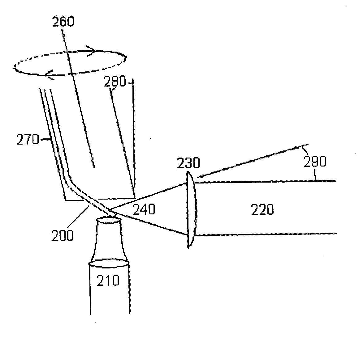
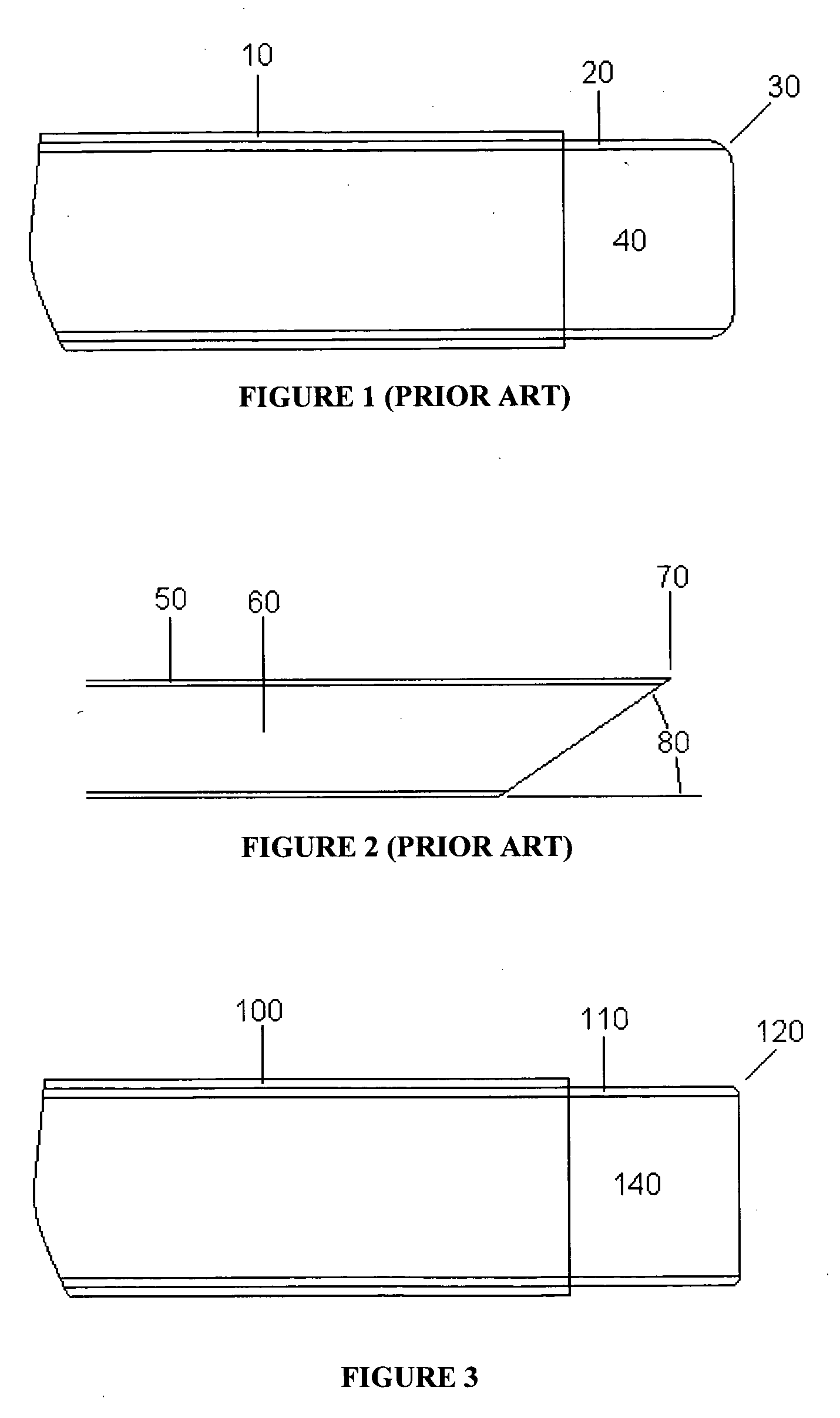
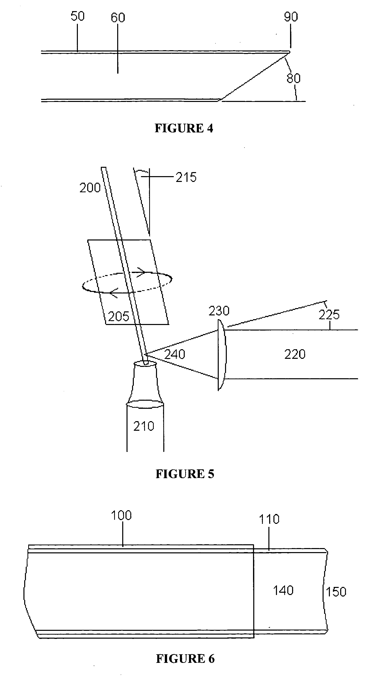
[0037] In prior art methods of laser processing bare fiber tips, the heat applied to the fiber—of sufficient concentration to produce the bulk vaporization and surface melt effects—conducts to the fiber edges where excessive rounding results. FIG. 1 illustrates the best case resulting from use of a CO2 laser to flat-polish a low CCDR fiber, where 10 is the fiber buffer coating (polymer), 20 is the doped glass cladding and 30 is edge rounding that distorts the silica core 40. In the simplest variation of the current art, illustrated in FIG. 5, the opening of a small vacuum tube 210 connected to a vacuum motor is positioned just below the focal point of the laser 240 on a fiber 200 with the fiber 200 centered in the vacuum tube opening in rotation. For flat polished surfaces, and concave, fiber 200 is located within collet 205 and is rotated at an angle 215 that is approximately the same as the focal angle 225 of the laser. The flow of air around the fiber 200 serves to cool the disto...


PUM

PropertyMeasurementUnit
Angleaaaaaaaaaa
Energy densityaaaaaaaaaa
Symmetric field theoryaaaaaaaaaa

Abstract

Fiber optic end faces produced by laser ablation, as opposed to “cleave” or mechanical polish, offer advantages in some severe environment applications such as laser surgery and delivery of extremely high energy density. The “laser polished” fiber faces are more resistant to physical damage as well as less prone to damage other structures, owing to a lack of sharp, fragile edges and laser polished faces may be formed on fibers in planes and curvatures normal to the fiber axis or off normal, as desired.

Description

FIELD OF THE INVENTION [0001] The present invention relates generally to applications of lasers to the processing of “bare” optical fiber ends (termini) and the application of fibers so terminated to laser surgery and in delivery of extreme energy density, where damage to traditionally prepared fiber termini occurs principally through laser damage, hydrothermal corrosion and metal ion catalyzed devitrification or combinations thereof. BACKGROUND OF THE INVENTION AND DESCRIPTION OF THE PRIOR ART [0002] Most fused silica optical fiber intended for use in high energy transmission is mechanically polished or “cleaved” (the latter being a misnomer since fused silica fiber is amorphous). Mechanically polished ends generally fail at high energy density by pitting, where the pits are thought to originate from stress foci or embedded polishing media that are artifacts of the mechanical polishing methods. Cleaved fibers are thought to perform best, but cleaves of adequate quality are difficul...

Claims


Application Information

Patent Timeline
IPC IPC(8): C03B37/07C03B37/15G02B6/32
CPCG02B6/262G02B6/4214
Inventor BARR, BRIAN D.GRIFFIN, STEPHEN E.
Owner INNOVA QUARTZ
Why Eureka
Try Eureka