Space vector-based current controlled pwm inverter for motor drives

a technology of space vector and inverter, which is applied in the direction of motor/generator/converter stopper, dynamo-electric converter control, dc motor speed/torque control, etc., can solve the problems of high switching loss, inability to design pmacms with unsurpassed efficiency characteristics, and irregular inverter operation

Active Publication Date: 2006-06-29
PROLIFIC TECH INC
View PDF7 Cites 36 Cited by
  • Summary
  • Abstract
  • Description
  • Claims
  • Application Information

AI Technical Summary

Benefits of technology

[0048] A main object of the present invention is to provide a motor drive technology of a space vector-based current controlled PW

Problems solved by technology

The use of permanent magnets to generate substantial air gap magnetic flux without excitation makes it possible to design PMACMs with unsurpassed efficiency characteristics.
However, to counterbalance these advantages, the sinusoidal PWM inverter control is complex, and the chopping frequency is high, which causes higher switching losses than the six-step operation.
However, among these techniques, the hysteresis current controller (HCC) is a rather popular one because of its easy implementation, fast dynamic response, maximum current limit, and insensitivity to load parameter variations.
Nevertheless, depending on load conditions, switching frequency may vary widely during the fundamental period, resulting in irregular inverter operation.
Moreover, high frequency and current peaking increase power loss and may affect system reliability.
However, the control algorithm is more complex and the main advantage of the HCC, i.e. the simplicity, is lost.
However, to obtain the zero-output-current error, the SVM technique requires a measurement of the counter emf vector which is not practical.
However, this approach is not economical.
However, this method introduces errors in the estimation of the third phase current because of the discrepancies in the gain constants and the DC offset of the other two current sensors.
However, under certain operating conditions of the PWM control, either two active

Method used


Image

  • Space vector-based current controlled pwm inverter for motor drives
  • Space vector-based current controlled pwm inverter for motor drives
  • Space vector-based current controlled pwm inverter for motor drives

Examples


Embodiment Construction

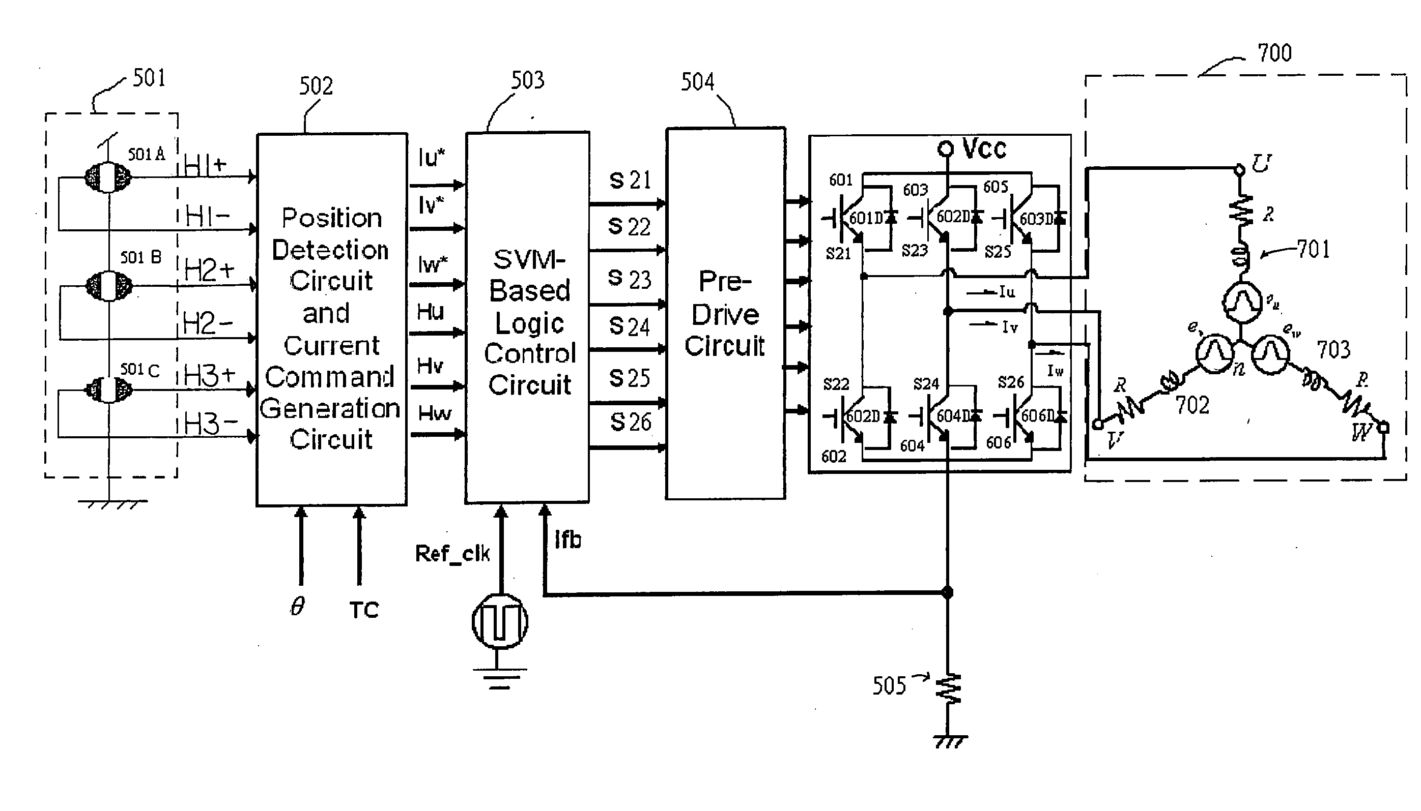
[0089] Referring to FIG. 19 of the drawings, FIG. 19 is a block diagram of a motor driver according to a preferred embodiment of the present invention in which the motor driver includes a Hall sensor circuit 501, a position detection circuit and current command generation circuit 502, a space vector modulation (SVM) based logic control circuit 503, a pre-drive circuit 504, a current detection resistor 505, and U-phase, V-phase, and W-phase upper side drive transistors 601, 603, and 605, U-phase, V-phase, and W-phase lower side drive transistors 602, 604, and 606, diodes 601D, 602D, 603D, 604D, 605D, and 606D. A motor includes a U-phase coil 701, a V-phase coil 702, and a W-phase coil 703.

[0090] In this embodiment N-type metal oxide semiconductor (NMOS) transistors are used as the drive transistors 601-606. The anode end and cathode end of the diode 601D are connected to the source terminal and drain terminal of the drive transistor 601 respectively. Likewise, the anode end and cath...


PUM


Abstract

A motor driver has a plurality of output circuits each having an upper side switch and a lower side switch connected in series for supplying a current to a motor. The motor driver includes a current detection resistor connected in series with the plurality of output circuits in common for detecting a current supplied to the plurality of output circuits, a position detection circuit for outputting a position signal corresponding to a position of a rotor of the motor, a current command generation circuit for generating a target current command signal based on the position signal and a predetermined phase angle in which a phase angle of the target current command signal is determined by the predetermined phase angle, and a space vector modulation based logic control circuit for commanding a plurality of output circuits that are set in a plurality of switches states for control of an electric motor.

Description

BACKGROUND OF THE PRESENT INVENTION [0001] 1. Field of Invention [0002] The present invention relates to a motor drive technology, and more particularly to a motor drive technology of a space vector-based current controlled PWM system. [0003] 2. Description of Related Arts [0004] Permanent magnet AC motors (PMACMs) have been widely adopted for high-performance servo applications, because of their desirable features: high efficiency, hight torque to inertia ratio, lower maintenance cost, and compact structure when compared to induction and brush DC motors. The use of permanent magnets to generate substantial air gap magnetic flux without excitation makes it possible to design PMACMs with unsurpassed efficiency characteristics. Such efficiency advantages are becoming increasingly valuable in many applications of the world. Since all of the PMACMs are synchronous machines, an average torque can be produced only when the excitation is precisely synchronized with the rotor speed and inst...

Claims


Application Information

Patent Timeline
IPC IPC(8): H02P7/36H02P27/00
CPCH02M7/53875H02M2007/53876H02P21/0032H02P21/34H02M7/53876
Inventor CHENG, KUANG-YAO
Owner PROLIFIC TECH INC
Why Eureka
Try Eureka