[0012] The fourth aspect of the invention relates to a microcup composition comprising an unsaturated
moiety or additive as an absorbing material for gases such as
chlorine,
hydrogen and
oxygen. The microcup composition may further comprise a catalyst for the hydrogenation or oxidation reaction. The use of a gas absorber in the microcup material improves the
longevity of the display.
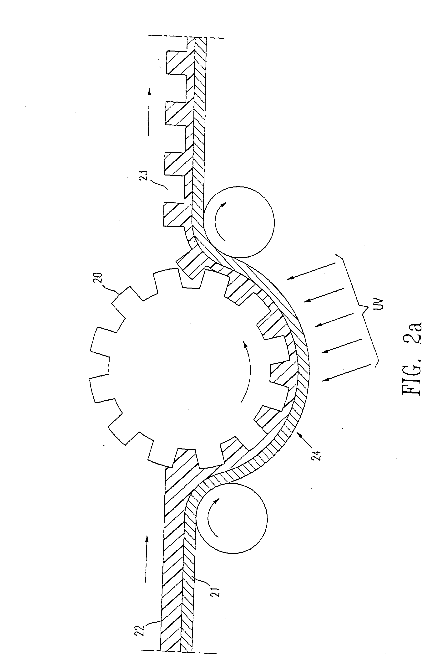
[0016] In either one of the two preferred methods, the sealing of the microcups is conveniently accomplished by hardening the sealing layer by
solvent evaporation,
interfacial reaction,
moisture, heat or
radiation. UV
radiation is the preferred method to harden the sealing layer, although a combination of two or more curing mechanisms as described above may be used to increase the
throughput of sealing. Additives such as surfactant, leveling agent, filler, binder,
viscosity modifier (
thinning agent or thickener), co-
solvent,
antioxidant, dye or
pigment may be added to the sealing composition to improve the display performance.
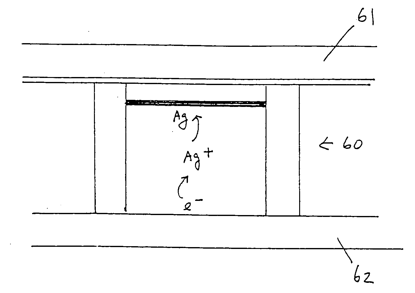
[0019] The eighth aspect of the present invention relates to the use of density-matched reflecting particles in microcup ECD's and
EDDs. The most preferred reflecting materials include TiO2, ZnO, BaSO4 and silica. They may be density-matched to the gel
electrolyte by a
polymer coating or microencapsulation method. The response rate of an ECD or EDD typically increases with decreasing
viscosity of the
electrolyte fluid. The use of density-matched reflecting particles eliminates the undesirable particle
sedimentation even in an electrolyte fluid of low
viscosity. As a result, the response rate of the display may be significantly improved without tradeoff in display
longevity and image uniformity.
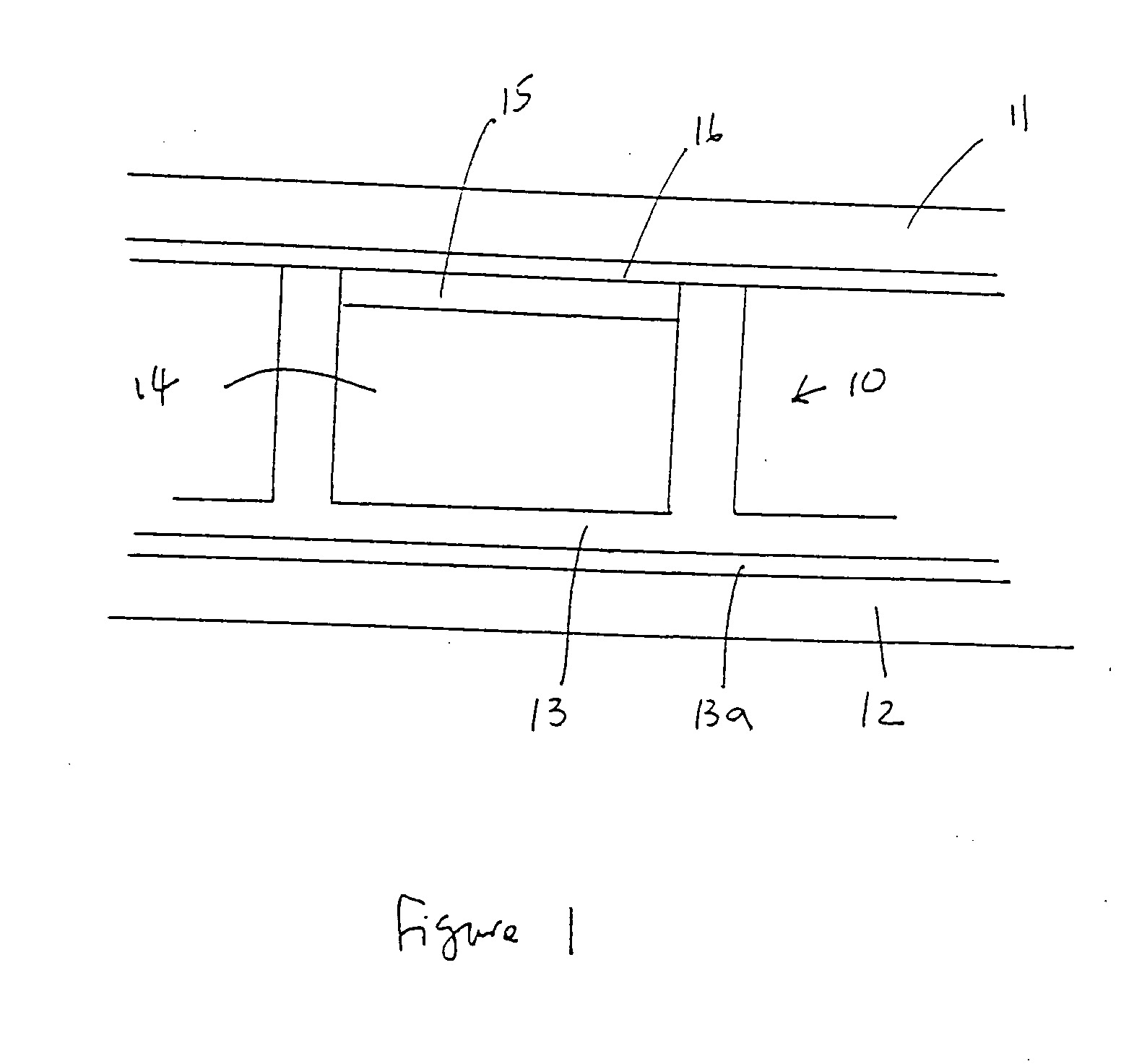
[0020] The electrodeposition or electrochromic display of the present invention has many advantages. One of them is that the microcup wall is in fact a built-in spacer to keep the top and bottom substrates apart at a fixed distance. The mechanical properties and
structural integrity of this type of display are significantly better than any prior art displays including those manufactured by using spacer particles. Moreover, displays involving microcups have desirable mechanical properties including reliable display performance when the display is bent, rolled or under
compression pressure from, for example, a touch screen application. The use of the microcup technology also eliminates the need of an edge seal
adhesive to predefine the size of the display panel and confine the electrolyte fluid inside a predefined area. The electrolyte fluid within the display of U.S. Pat. No. 6,336,753 and the SID 02 Digest, pp. 39-41 publication prepared by the edge sealing
adhesive method will leak out completely if the display is
cut in any way, or if a hole is drilled through the display. The damaged display will be no longer functional. In contrast, the electrolyte fluid within the display prepared by the microcup technology is enclosed and isolated in each
cell. The microcup display may be
cut into any dimension without the risk of damaging the display performance due to the loss of electrolyte fluid in the active areas. Furthermore, the microcup structure enables a format
flexible display manufacturing process wherein the process may be carried out roll-to-roll on a web continuously or semi-continuously.
[0021] The isolated microcup or
cell structure is particularly important when cells are filled with electrolyte fluids of different specific properties such as switching rate,
reflectivity, color and color density. Without the microcup structure, it will be very difficult to prevent the fluids in adjacent areas from intermixing or being subject to cross talk during operation. As a result, the bistable reflective display of this invention also has excellent color
addressability and switching performance. In addition, the electrodeposition and electrochromic displays according to the present invention could be very thin, flexible and durable and may be manufactured at very low cost by a roll-to-roll and format flexible process.

