Pulse width modulation amplifier
a pulse width modulation and amplifier technology, applied in pulse techniques, instruments, recording signal processing, etc., can solve the problems of many components and complex circuits, inability to follow the miniaturization of semiconductor processes, and difficulty in performing feedback operations for reducing output noise, etc., to achieve low cost, low cost, and low cost
- Summary
- Abstract
- Description
- Claims
- Application Information
AI Technical Summary
Benefits of technology
Problems solved by technology
Method used
Image


Examples
first embodiment
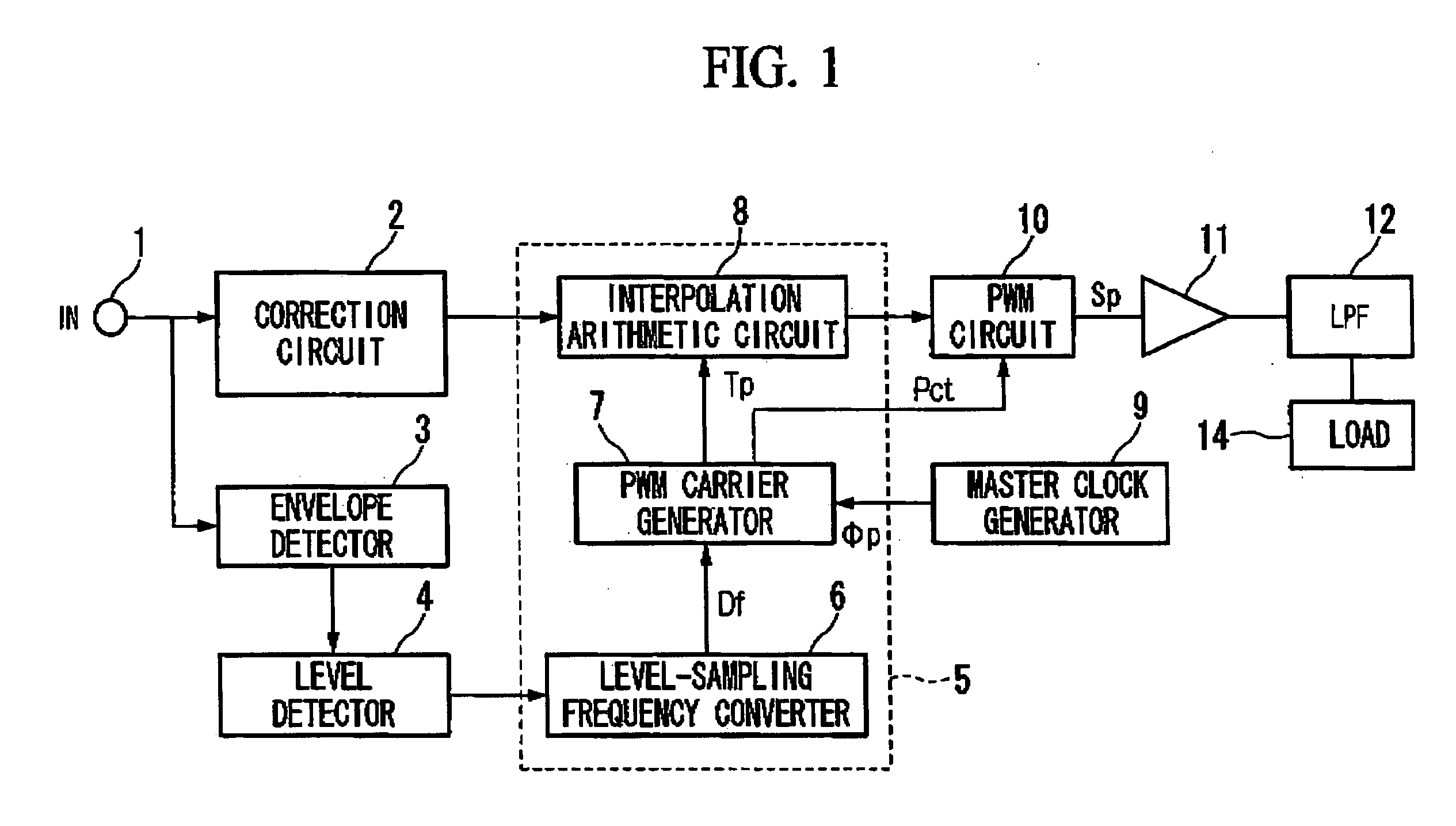
[0038]FIG. 1 is a block diagram for illustrating a structure of a pulse width modulation amplifier of a first embodiment in accordance with the invention. The pulse width modulation amplifier is a circuit in which an input signal (digital) is converted to a pulse-width modulated signal to be amplified and output.
[0039] In FIG. 1, reference numeral 1 represents an input terminal to which PCM musical sound data is applied, and 2 shows a correction circuit. The correction circuit 2, which is publicly known in prior art, includes a distortion correction circuit for correcting distortion of PWM, a frequency characteristic correction circuit, and a ΔΣ correction circuit for controlling quantization noise, for the input digital data. Reference numeral 3 designates an envelope detector that detects an envelope of the PCM musical sound data to be applied to the input terminal 1, which in turn is supplied to a level detector 4.
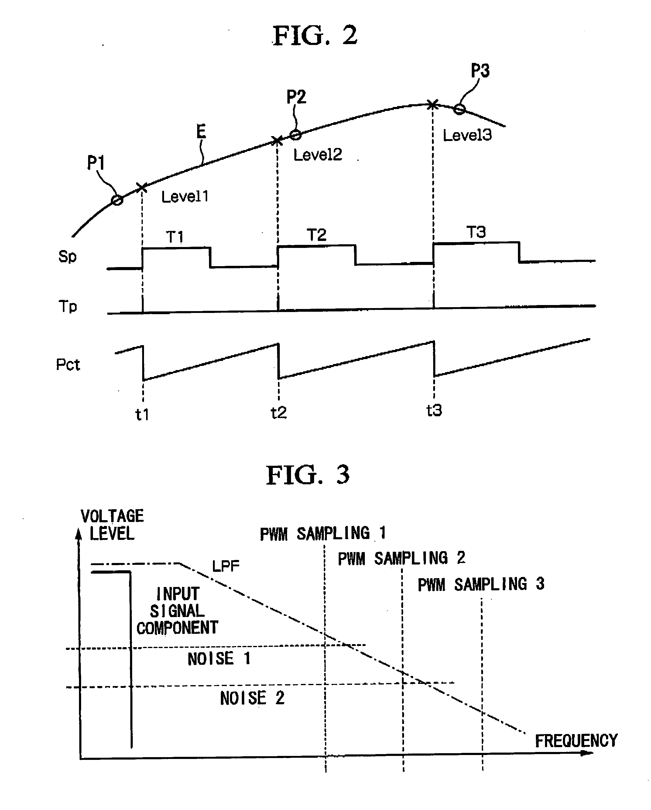
[0040]FIG. 2 shows the PCM musical sound data and the envelope th...
second embodiment
[0060] A second embodiment in accordance with the invention will be described below.
[0061]FIG. 6 is a block diagram for illustrating a structure of a pulse width modulation amplifier of the second embodiment. In FIG. 6, reference numeral 21 represents an input terminal to which the PCM musical sound data is applied. Reference numeral 22 designates a correction circuit that is the same as the correction circuit 2 in FIG. 1. The musical sound data output is supplied to a PWM circuit 23. Reference numeral 24 represents an input terminal to which the master clock Φp is applied. Reference numeral 25 denotes a differential PLL (phase locked loop). The differential PLL multiplies the master clock Φp and outputs the multiplied master clock as a differential clock pulse. One phase of the clock pulse is supplied to the PWM circuit 23, while the differential clock pulse is provided to a latch circuit (also referred to as a “latch”) 26.
[0062] The PWM circuit 23 generates a PWM carrier data tha...
third embodiment
[0066] A third embodiment in accordance with the invention will be described below.
[0067]FIG. 10 is a block diagram for illustrating a structure of a pulse width modulation amplifier of the third embodiment in accordance with the invention. In the figure, the same reference numerals are assigned to the structural elements that are the same as those in FIG. 1.
[0068] In the figure, reference numeral 1 designates the input terminal to which musical sound Xin is supplied. The musical sound Xin is interpolated and processed by the interpolation arithmetic circuit 8, as described above regarding FIG. 1 to be supplied to a PWM circuit 41. The PWM circuit 41 converts an output X from the interpolation arithmetic circuit 8 to a pulse width modulation signal Sp, which is fed to the load 14 such as a sped via the amplifier 14 and the LPF.
[0069] A reference numeral 42 is a absolute value output circuit, which receives data X from the interpolation arithmetic circuit 8, supplies an absolute va...
PUM
 Abstract
Description
Claims
Application Information
 - R&D
- Intellectual Property
- Life Sciences
- Materials
- Tech Scout
- Unparalleled Data Quality
- Higher Quality Content
- 60% Fewer Hallucinations
Browse by: Latest US Patents, China's latest patents, Technical Efficacy Thesaurus, Application Domain, Technology Topic, Popular Technical Reports.
© 2025 PatSnap. All rights reserved.Legal|Privacy policy|Modern Slavery Act Transparency Statement|Sitemap|About US| Contact US: help@patsnap.com