Piezoelectric sensor arrangement

a technology of piezoelectric resonators and sensors, which is applied in the field of piezoelectric sensor arrangements, can solve the problems of affecting the resonance behaviour of the piezoelectric resonator, the resonator's resonating behaviour may be impaired, and the use of piezoelectric resonators in these areas has not gained commercial acceptance, so as to achieve the effect of reducing manufacturing costs and being easy to handl

Active Publication Date: 2006-06-29
ATTANA AB
View PDF9 Cites 16 Cited by
  • Summary
  • Abstract
  • Description
  • Claims
  • Application Information

AI Technical Summary

Benefits of technology

[0015] In comparison to the conventional liquid connection systems, which use flow cells composed of a plurality of components, such as the one in U.S. Pat. No. 6,196,059 B1, manufacturing costs are lowered. This is an essential advantage, since the sensor crystals are made only for single use and must be disposed of after use. In addition, the sensor arrangement of the present invention is very easy to handle, since the user does not need to possess any personal skill to assemble the flow cell.
[0016] The present invention also relates to a sensor element for analysis of fluid samples in a piezoelectric sensor arrangement, which comprises a carrier to which a piezoelectric quartz crystal is attached, said crystal having a front side and a rear side, where said f

Problems solved by technology

The use of piezoelectric resonators in these areas has up to now not gained a commercial acceptance, due to the drawbacks of the hitherto available systems.
However, due to the structure of the small plates, the resonating behaviour of the resonator may be impaired, i.e. by mechanical tension in the small plates caused by the holding carriers or by contacting with electric lines.
A disadvantage of this arrangement is that even with the least exerted force, acting on the two parts, which are spaced apart, a mechanical tension can be generated in the small plate glued between parts, thereby influencing its resonance behaviour.
However, the use of conductive adhesives has the consequence that the electric contact cannot be disconnected, which, for instance, makes replacing the small oscillator quartz plate impossible or at least requires great manual skill.
The small oscillator quartz plates are glued to or clamped in a holding means, which can impair the resonance behaviour of the resonator itself

Method used


Image

  • Piezoelectric sensor arrangement
  • Piezoelectric sensor arrangement
  • Piezoelectric sensor arrangement

Examples


Embodiment Construction

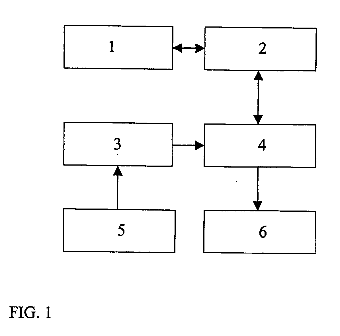
[0030] The piezoelectric sensor arrangement of the present invention is intended to be a part of an analysis system, which is shown in FIG. 1, for sensing chemicals and chemical reactions in liquids. Such an analysis system comprises a computer (PC) 1 for controlling and presenting data, a frequency counter 2, a sample insertion unit 3, a sensor arrangement 4, a buffer solution container 5 and a waste container 6.

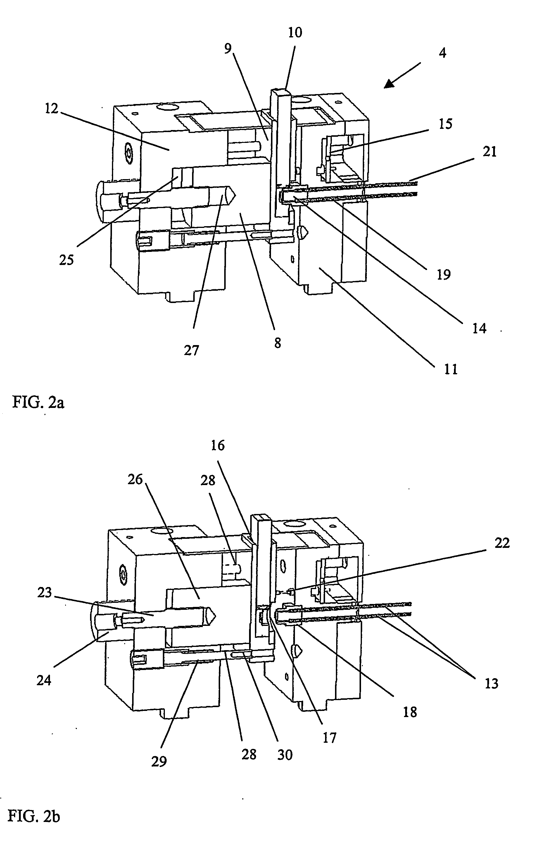
[0031]FIGS. 2a and 2b show a piezoelectric sensor arrangement 4 according to a preferred embodiment of the invention. The arrangement comprises a docking system, which includes a first part 8 provided with means 9 for receiving a sensor element 10 and a second part 11, 12, which comprises fluid channels 13 for the sample and a flow cell element 14. The flow cell element is preferably removable. The first and second parts are movable in relation to each other between a closed position (FIG. 2a) and an open position (FIG. 2b). The sensor element 10 exposes a piezoelectric qu...


PUM


Abstract

A piezoelectric sensor arrangement for analysis of fluid samples includes a signal source, a measuring device and a docking system. The sensor arrangement comprises a first part provided with means for receiving a sensor element that exposes a piezoelectric quartz crystal, a second part comprising fluid channels for the sample and a flow cell element, which preferably is removable and which comprises a recess, and inlet and outlet fluid channels for leading a fluid through the recess. The first and second parts are movable in relation to each other between a closed position and an open position and are arranged such that in the closed position the recess of the flow cell element is sealingly covered by the piezoelectric quartz crystal so that a flow cell is formed by said flow cell element and the quartz crystal.

Description

TECHNICAL FIELD [0001] The present invention relates to a piezoelectric sensor arrangement, a sensor element and a flow cell element to be used in the sensor arrangement. BACKGROUND [0002] A Quartz Crystal Microbalance (QCM) system utilizes the piezoelectric effect of a quartz crystal. In such a system a quartz crystal that is placed between two electrodes, which are connected to an AC-potential, begins to oscillate if the frequency of the AC-potential is close to the resonance frequency of the oscillation mode for the quartz crystal. The resonance frequency of the quartz crystal is a function of many parameters, such as temperature, pressure, cut angel of the crystal, mechanical stress and thickness of the crystal. The resonance frequency is inversely proportional to the square root of the thickness of the crystal as described by the Saurbrey equation: Δ⁢ ⁢f=-2⁢f2ρ⁢ ⁢v⁢Δ⁢ ⁢mA where f is the resonance frequency, ρ the density of quartz, v the shear wave velocity in quartz, A the el...

Claims


Application Information

Patent Timeline
IPC IPC(8): C12M1/34G01N27/00
CPCG01N29/036G01N2291/0256
Inventor AASTRUP, TEODORSMITH, JANANDERSON, HENRIK
Owner ATTANA AB
Why Eureka
Try Eureka