Indirect evaporative cooling heat exchanger

a heat exchanger and evaporative cooling technology, applied in the direction of machines/engines, heating types, lighting and heating apparatus, etc., can solve the problems of long assembly period, high cost, and difficult repeatability of manufacturing methods, and achieve the effect of low cost and easy repeatability of manufacturing

Active Publication Date: 2006-07-06
MUNTERS THE
View PDF15 Cites 3 Cited by
  • Summary
  • Abstract
  • Description
  • Claims
  • Application Information

AI Technical Summary

Benefits of technology

[0011] Various embodiments of the systems and methods according to this invention provide IEC heat exchangers that are relatively economical to manufacture and relatively quick to assemble.
[0016] Various embodiments of the systems and methods according to the invention separately provide IEC heat exchangers that have a wet side surface that is wettable, can be kept free of mineral deposits even though hard water intermittently sprayed on a surface of the heat exchanger, and can be manufactured at a cost that allows an ICE containing the heat exchanger to compete ton for ton of air conditioning with standard mechanical air conditioning.
[0019] Various embodiments of the systems and methods according to the invention provide IEC heat exchange methods of manufacture that achieve relatively low cost assembly of heat exchanger components and easy repeatability of manufacture of such components by relatively unskilled labor.
[0020] Various embodiments of the systems and methods according to the invention provide IEC heat exchange methods of manufacture including angling the exchange tubes at a bottom end so that the tubes enter a cut out portion of a header plate of the heat exchanger with ease.

Problems solved by technology

Such wet environments are known to contain a wide range of contaminants and are often corrosive to IEC components.
As a result of the hostile environment that such IEC heat exchangers witnessed, they were maintenance prone and short lived.
Additionally, known heat exchangers have designs that require lengthy assembly periods.
This method of assembly often requires 10-20 hours to implement.
Furthermore, extensive quality assurance is also necessary due to the possibility of leaks.

Method used


Image

  • Indirect evaporative cooling heat exchanger
  • Indirect evaporative cooling heat exchanger
  • Indirect evaporative cooling heat exchanger

Examples


Embodiment Construction

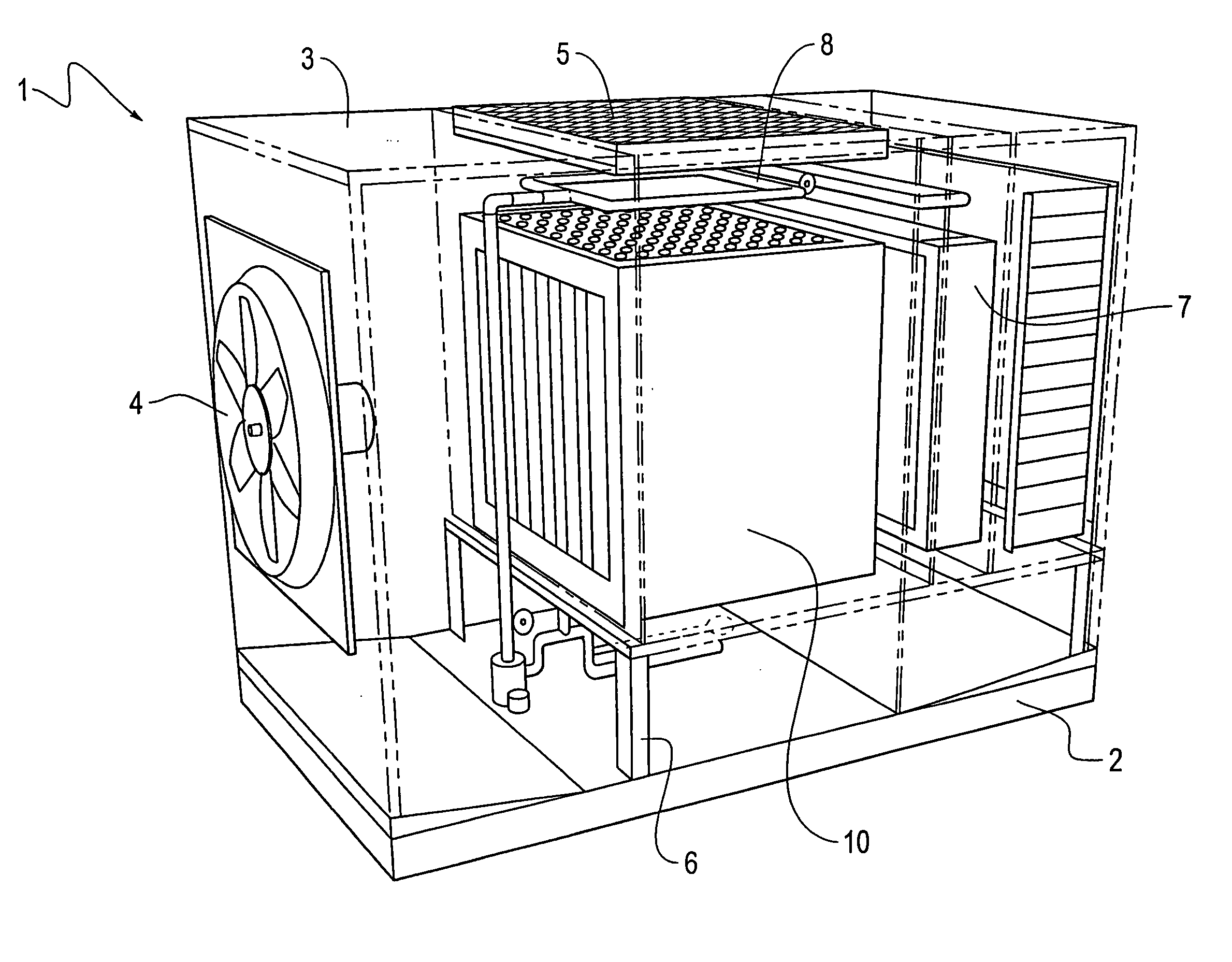
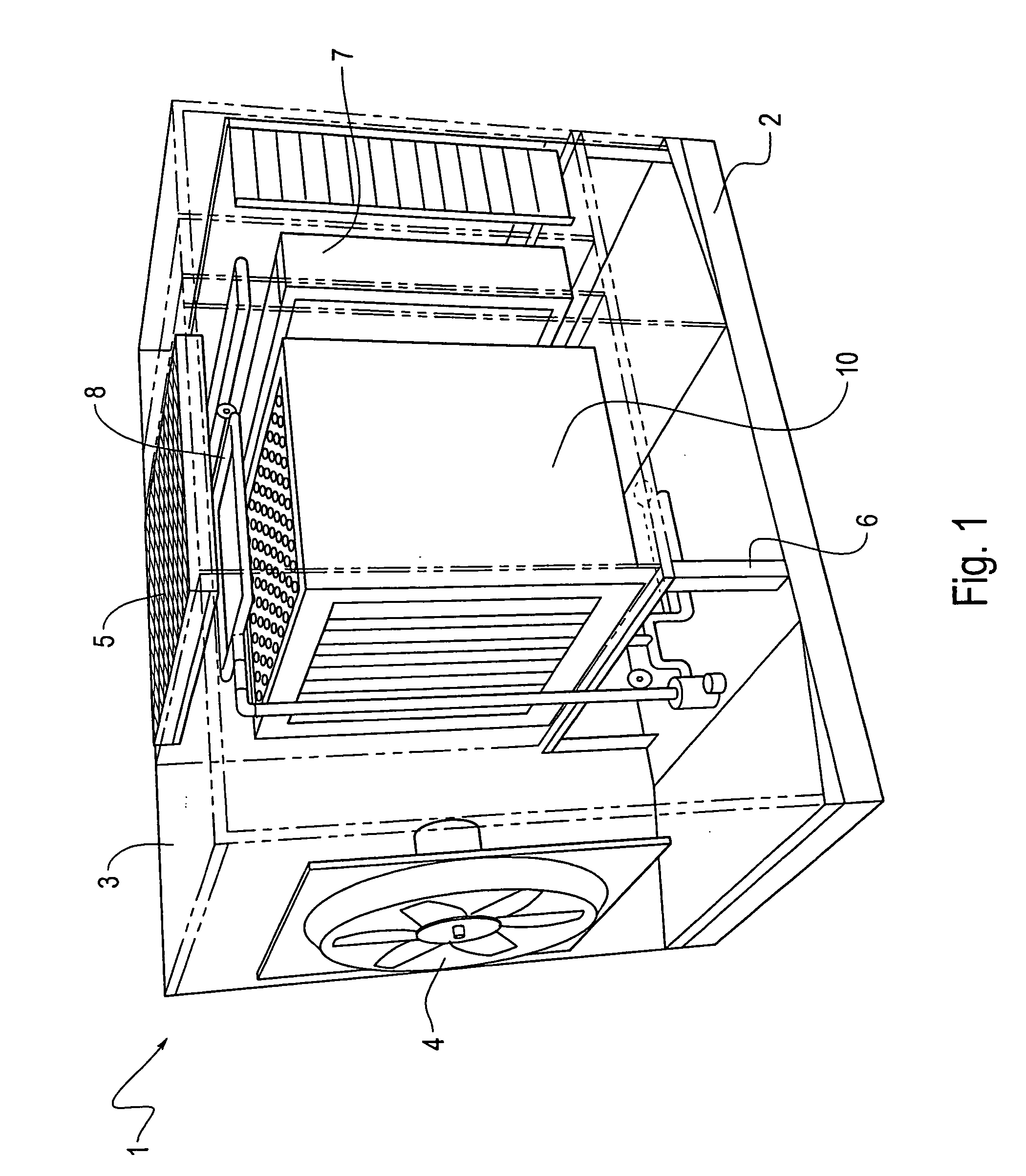
[0031]FIG. 1 is a perspective view of an indirect / direct evaporative cooling unit, including an indirect evaporative cooler heat exchanger, according to an exemplary embodiment of the invention. As shown in FIG. 1, an indirect / direct evaporative cooling unit 1 includes, a base portion 2, a frame 3, and an air intake fan 4 mounted in a wall of the frame 3 at one end of the unit 1. The intake fan 4 provides outside air to the unit 1. The unit 1 further includes an exhaust grate 5 mounted in the top of the unit 1 to allow high energy, unconditioned air to exit the unit 1.

[0032] A support frame 6 is mounted to the base portion 2 within the unit 1 to provide a mounting point for the indirect heat exchanger 10 and the direct cooling stage 7. A water distribution manifold 8 is disposed over the indirect heat exchanger 10 and the direct cooling stage 7 to deliver water thereto. In other words, the unit shown in FIG. 1 includes all the devices that are necessary for proper operation to cool...


PUM

PropertyMeasurementUnit
widthaaaaaaaaaa
chord lengthaaaaaaaaaa
wall thicknessaaaaaaaaaa

Abstract

A heat exchanger including a header having a plurality of header openings with rigid tubes that may be made of plastic are inserted in the openings. The tubes are sealed to the header to prevent leakage between the header and the tubes to prevent water and air leakage between the wet, scavenger air stream flowing through the tubes and a dry air stream flowing around the tubes. A method of making the heat exchanger includes providing the openings with a flange and uses an interference fit between the rigid heat exchange tubes and the header openings. A self-leveling sealant may be used to seal the heat exchanger tubes to the header using, for example, a paint roller and / or a paint sprayer.

Description

[0001] This is a Division of application Ser. No. 10 / 853,160 filed May 26, 2004. The entire disclosure of the prior application is hereby incorporated by reference herein in its entirety.BACKGROUND OF THE INVENTION [0002] 1. Field of Invention [0003] This invention relates to indirect evaporative cooling technology, and particularly to heat exchangers useful in indirect evaporative cooling devices used for conditioning air. [0004] 2. Description of Related Art [0005] Evaporative cooling involves lowering the temperature of a liquid by utilizing the latent heat of vaporization of a portion of the liquid. The term “Indirect Evaporative Cooling” was coined by personnel at Des Champs Laboratories in 1974, when they decided to enhance summer-time air-to-air energy recovery, from building exhaust air, by utilizing the wet bulb temperature of the exhaust air instead of the higher dry bulb temperature. At the time, it was common practice during summer months to transfer energy from the cool...

Claims


Application Information

Patent Timeline
Patent Type & Authority Applications(United States)
IPC IPC(8): F28F13/00B21D53/06B21K21/00B23P15/26F24F1/0043F28D5/00F28F1/10F28F1/40F28F9/14F28F9/16F28F9/26F28F21/06
CPCB23P15/26Y10T29/49377F28F1/40F28F9/14F28F9/162F28F21/062Y02B30/545Y10T29/49359Y10T29/49373Y10T29/49378Y10T29/49384Y10T29/49364Y10T29/4938Y10T29/4935F24F2001/0092F24F1/0007F28C3/08F24F1/0043F24F1/0059Y02B30/54
Inventor DES CHAMPS, NICHOLAS H.
Owner MUNTERS THE
Why Eureka
Try Eureka