

Power semiconductor device and method of manufacturing the same
- Summary
- Abstract
- Description
- Claims
- Application Information
AI Technical Summary
Benefits of technology
Problems solved by technology
Method used
Image

Examples
Embodiment Construction
[0035] The power semiconductor device in accordance with the present invention and a method for manufacturing thereof will now be described with reference to several illustrative applications and embodiments.
[0036] Although in the following description the layers and regions will be described as having certain conductivity types and being compared of certain materials, this is for illustrative purposes only. It is not intended that the invention be limited to the specific conductivity types or the specific materials referred to herein.
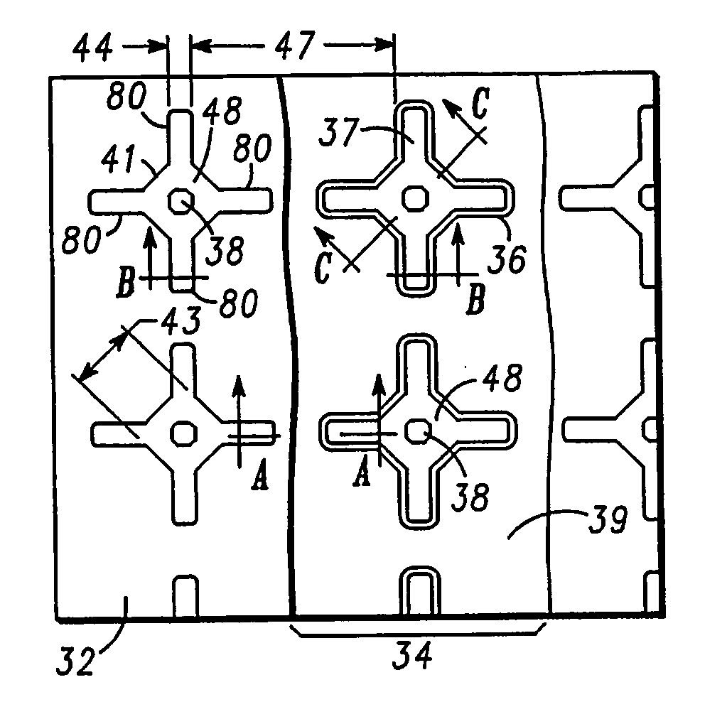
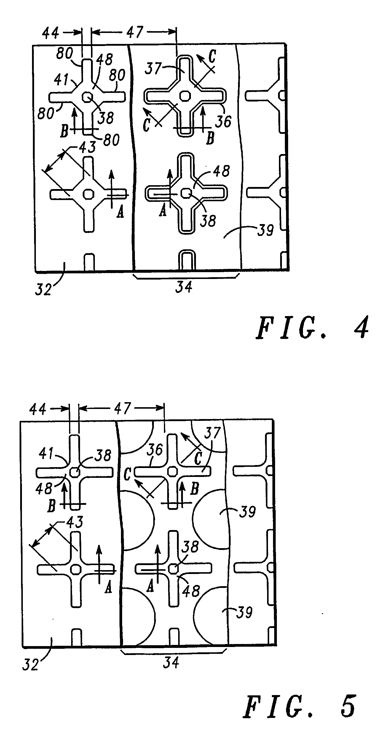
[0037]FIG. 4 depicts in more detail a top view of individual cells with four branches arranged crosswise of a semiconductor device according to an embodiment of the present invention before the merge operation. This arrangement aims at having improved channel density and low on-state resistance.
[0038] As is shown in FIG. 4, each individual cell has two horizontal branches and two vertical branches. The four branches of each individual cell are arran...
PUM
 Abstract
Description
Claims
Application Information