Micro-electromechanical relay and related methods

Inactive Publication Date: 2006-07-06
NORCADA
View PDF14 Cites 40 Cited by
  • Summary
  • Abstract
  • Description
  • Claims
  • Application Information

AI Technical Summary

Benefits of technology

[0012] The present invention is directed to a micro-electromechanical relay that can produce low electrical resistance at the metal-metal contacts and is capable of mechanical latching. More specifically, the present micro-electromechanical relay combines actuating cantilever beams with a moveable shuttle-like spacer structure to generate high contact forces at the

Problems solved by technology

The high contact forces produce larger metal-metal contact a

Method used


Image

  • Micro-electromechanical relay and related methods
  • Micro-electromechanical relay and related methods
  • Micro-electromechanical relay and related methods

Examples


Example

[0026] The present invention can be described in more detail with reference to the accompanying figures in which two preferred embodiments of the invention are shown and two methods of fabrication are illustrated. It should be understood, however, that there is no intent to limit the invention to the particular embodiments and methods disclosed, but on the contrary, the invention is to cover all modifications, equivalents, and alternatives falling within the scope of the invention as defined by the claims.

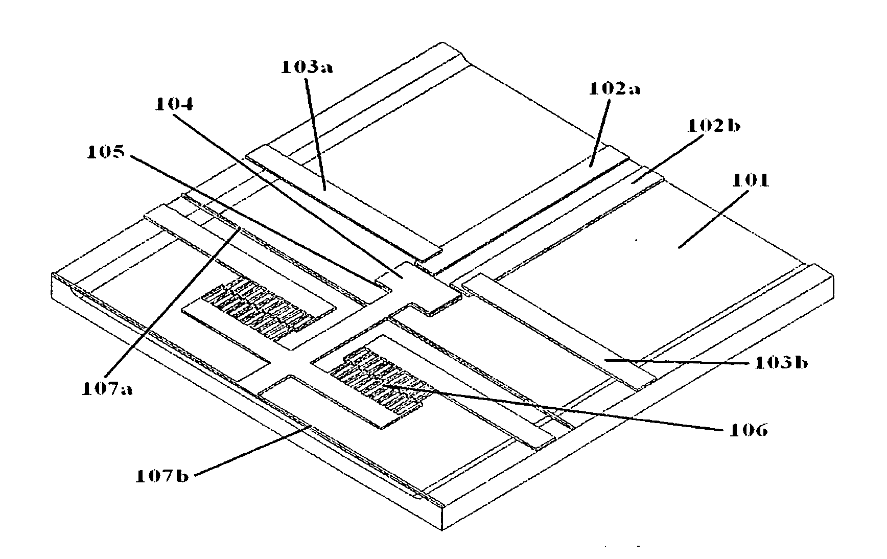
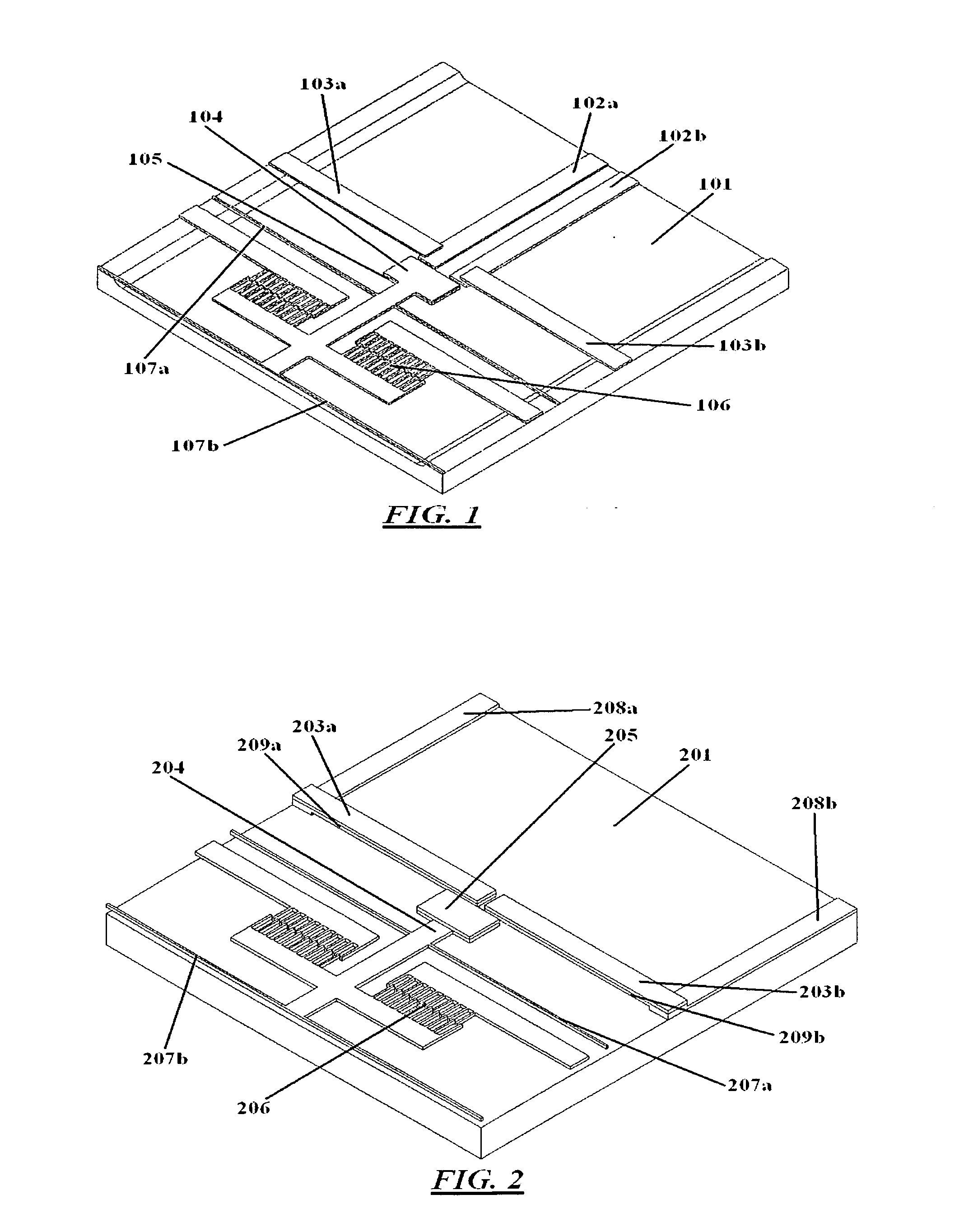
[0027]FIG. 1 is a diagrammatic isometric view of a micro-electromechanical relay in accordance with one embodiment of the present invention. The relay comprises a base substrate 101, fixed conductors 102a, 102b disposed onto the base substrate, cantilever beams 103 attached to the base substrate at their fixed ends and suspended over the fixed conductors at their free ends, and a movable shuttle structure 104 attached to a shuttle actuator 106. The fixed part of the shuttle actuat...


PUM

PropertyMeasurementUnit
Temperatureaaaaaaaaaa
Thicknessaaaaaaaaaa
Sizeaaaaaaaaaa

Abstract

The present invention provides a micro-electromechanical relay that can produce low electrical contact resistance, and is capable of mechanical latching. More specifically, the present invention combines the clamping actions of cantilever beams with a movable shuttle-like spacer to generate high contact forces at the metal-metal contacts of the micro-electromechanical relay, thereby producing a very low electrical contact resistance and a mechanism for mechanical latching. Methods of fabricating the micro-electromechanical relay are also provided in this invention, which offer the advantages of both design and fabrication flexibilities by processing the top and bottom substrates separately prior to joining them together.

Description

BACKGROUND OF THE INVENTION [0001] The present invention relates to a micro-electromechanical relay that combines clamping cantilever beams with movable shuttle structure to provide strong contact force, latching mechanism, and high standoff voltage. [0002] Micro-electro-mechanical system or MEMS refers to micro devices that typically integrate electrical and mechanical elements on a common substrate or substrate stack using microfabrication technology. The electrical elements are typically formed using metal film deposition and patterning techniques, and the mechanical elements are normally fabricated using micromachining techniques which include deposition, lithographic patterning, and etching of various structural and sacrificial materials. Wafer bonding or mating techniques to form multi-layer substrate stack is also commonly used in the fabrication of MEMS devices. Examples of MEMS devices include accelerometers, pressure sensors, micro mirror arrays and MEMS switches to name a...

Claims


Application Information

Patent Timeline
IPC IPC(8): H01H51/22
CPCH01H59/0009H01H61/02Y10T29/49147Y10T29/49083Y10T29/49155H01H2061/006
Inventor NING, YUEBINMCKINNON, GRAHAM HUGHHOWEY, CAMERON RAYMONDCOLGAN, MICHAEL JOHN
Owner NORCADA
Why Eureka
Try Eureka