
Miniaturized utility device having integrated optical capabilities

a utility device and optical capability technology, applied in the field of miniaturized imaging devices, can solve the problems of unreliability, cost and slow, inability to fit the transducer, and limited visual capabilities used to perform utilitarian functions, and achieve the effect of high aspect ratio and high aspect ratio system

Inactive Publication Date: 2006-07-06
STERLING L C
View PDF98 Cites 87 Cited by
  • Summary
  • Abstract
  • Description
  • Claims
  • Application Information

AI Technical Summary

Benefits of technology

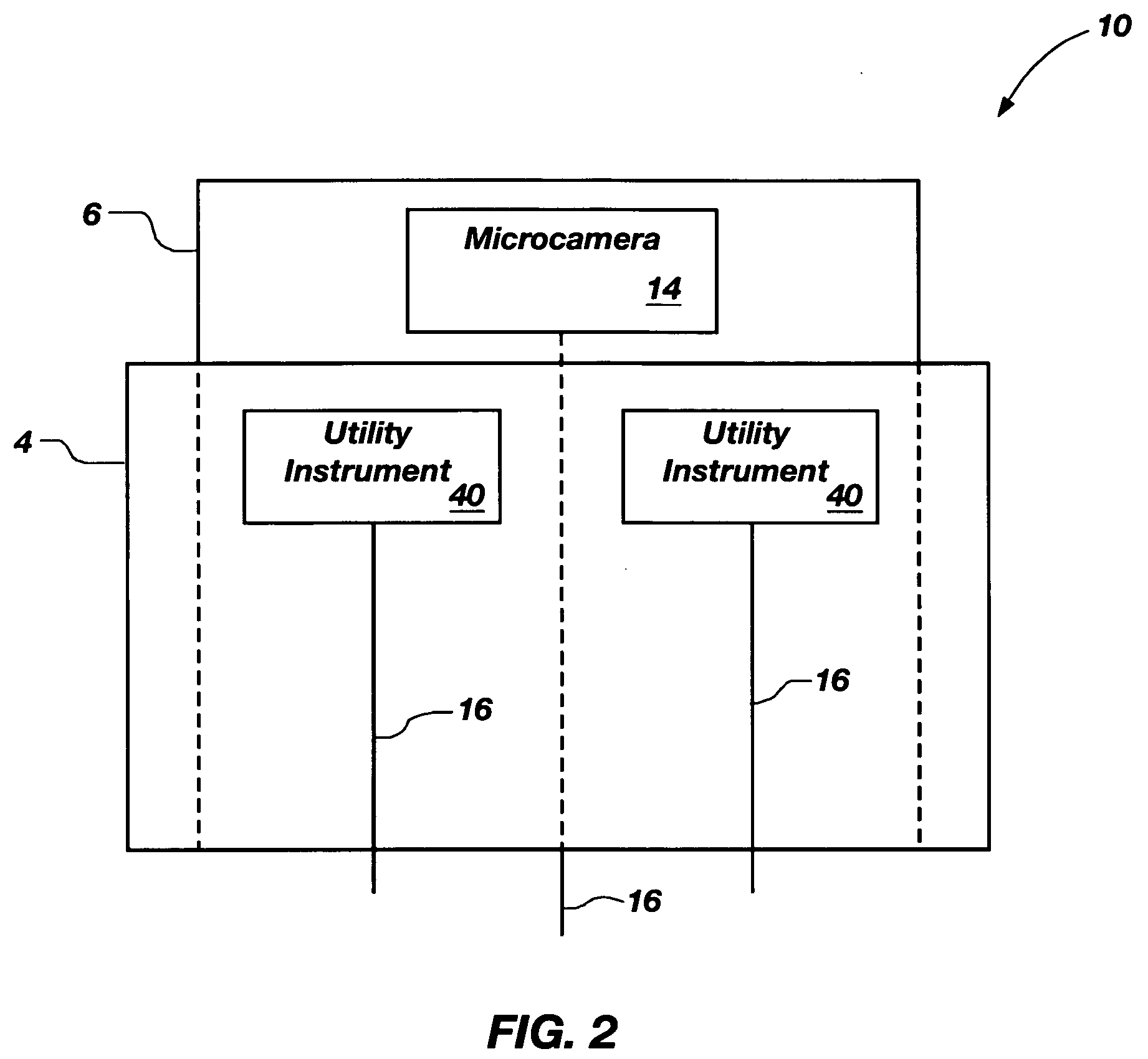
[0009] In accordance with the invention as embodied and broadly described herein, what is featured is a miniaturized utility device having integrated optical capabilities, preferably for use on a high aspect ratio system, wherein the miniaturized utility device comprises: (a) an imaging device comprising a utility guide supported at the distal end of a high aspect ratio system, wherein the utility guide has a plurality of utility apertures formed therein; a solid state imaging device carried by the utility guide, wherein the solid state imaging device has an imaging array on a top surface, and a conductive element on a side surface, wherein the imaging array is electrically coupled to the conductive element; (b) a lens optically coupled to the imaging array to form a micro camera; (c) a micro utility instrument operably supported within one of the utility apertures of the utility guide for coordinated operation with the micro camera at a local site, wherein the micro utility instrument is configured to perform a designated function viewable in real-time via a camera image generated by the micro camera; and (d) an umbilical carried by at least one of the apertures and comprising a plurality of transfer elements, including a conductive line, for operably connecting the micro camera and the micro utility instrument, wherein the conductive line is electrically coupled to the conductive element on the side surface of the solid state imaging device.
[0010] The present invention further features a miniaturized utility system having integrated optical capabilities for use on a high aspect ratio system, wherein the miniaturized utility system comprises: (a) a utility guide supported at a distal end of a first high aspect ratio system, wherein the utility guide has a plurality of utility apertures formed therein; (b) a solid state imaging device carried by the utility guide, wherein the solid state imaging device comprises an imaging array on a top surface, and a conductive element on a side surface, such that the imaging array is electrically coupled to the conductive element; (c) a lens optically coupled to the imaging array to form a micro camera; and (d) a micro utility instrument operably supported on a distal end of a second high aspect ratio system configured to interact with the first high aspect ratio system to provide coordinated operation of the micro utility instrument with the micro camera at a local site, wherein the micro utility instrument is configured to perform a designated function viewable in real-time via a camera image generated by the micro camera.
[0011] The present invention still further features a miniaturized utility device having integrated optical capabilities for use on a high aspect ratio system, wherein the miniaturized utility device comprises: (a) a micro camera comprising a solid state imaging device including, as an integral structure, an imaging array electrically coupled to a conductive pad, wherein the solid state imaging device further includes at least one utility aperture passing therethrough; a lens optically coupled to the imaging array; and (b) a micro utility instrument configured for coordinated operation with the imaging device at a local site, wherein the micro utility instrument is configured to perform a designated function viewable, preferably in real-time, via a camera image generated by the micro camera.
[0012] The present invention still further features a miniaturized utility device having integrated optical capabilities comprising: (a) a plurality of solid state imaging devices supported along a length of a high aspect ratio system, each of the solid state imaging devices comprising at least one imaging array disposed on a top surface, and a conductive element on a side surface, wherein the imaging array is electrically coupled to the conductive element; (b) a plurality of lenses optically coupled to the imaging arrays to form a plurality of micro cameras; (c) a plurality of micro utility instruments configured for coordinated operation with the micro cameras at a plurality of local sites, wherein each of the micro utility instruments are configured to perform a designated function viewable in real-time via a camera image generated by the micro cameras; and (d) a plurality of transfer elements for operably connecting the micro cameras and the micro utility instruments.
[0013] The present invention also features various methods of operation. In one exemplary embodiment, the present invention features a method of operating a miniaturized utility device having optical capabilities, wherein the method comprises: (a) optically coupling a lens to an imaging array of a solid state imaging device to form a micro camera supported on a high aspect ratio system; (b) defining a plurality of conductive paths; (c) powering the solid state imaging device through a first of the conductive paths; (d) coordinating, at a local site, the performance of a utilitarian function with the operation of the micro camera, wherein the utilitarian function is performed by a micro utility instrument supported by the high aspect ration system; (e) transmitting a signal from the solid state imaging device through another conductive path, wherein the signal corresponds to a captured image of the local site or the targeted object at which the utilitarian function is being performed; and (f) processing the signal received from the solid state imaging device to form a camera image of the local site or the targeted object.
[0014] Another method featured is a method for performing a viewable utilitarian function at one or more local sites within a lumen comprising: (a) inserting a high aspect ratio device into a luminal opening, wherein the high aspect ratio system comprises at least one micro camera including a lens optically coupled to an imaging array of a solid state imaging device; (b) illuminating, at least partially, a local site around the lens within or beyond the luminal opening; (c) receiving light or photon energy in the lens reflected by contents within or beyond the luminal opening, thereby providing focused light or photon energy at the imaging array; (d) coordinating, at the local site, the performance of a utilitarian function with the operation of the micro camera, wherein the utilitarian function is performed by a micro utility instrument supported by the high aspect ratio system; (e) converting the focused light or photon energy to digital data that corresponds to a captured image of the local site at which the utilitarian function is being performed; and (f) processing the digital data into a camera image of the local site for viewing on a viewing source remote from the micro camera.

Problems solved by technology

However, due to the enclosure and small size of the micro environment, visual guidance of the high aspect ratio system, as well as the visual capabilities used to perform the utilitarian function have been limited.
Biplane fluoroscopy, however, is unreliable, costly and slow.
However, a drawback to this system is that the stenosis is often so severe that the transducer will not fit into the are that the interventional practitioner needs to explore the most.
Indeed, if the occlusion is too severe to be crossed by a guide wire, it may be too difficult to steer the transducer into the segment of greatest interest.
Additionally, an attempt to force an imaging catheter into a severely stenosed artery may have undesirable consequences.
However, there is not always a vein properly situated for such imaging.
Perhaps the most inherent drawback to each of these systems is their unilateral application.
Either way, these methods are extremely intrusive to the patient, they add additional time and expense to the procedure, and they are still limited in their viewing or image generating capabilities.

Method used


Image

  • Miniaturized utility device having integrated optical capabilities
  • Miniaturized utility device having integrated optical capabilities
  • Miniaturized utility device having integrated optical capabilities

Examples


example one

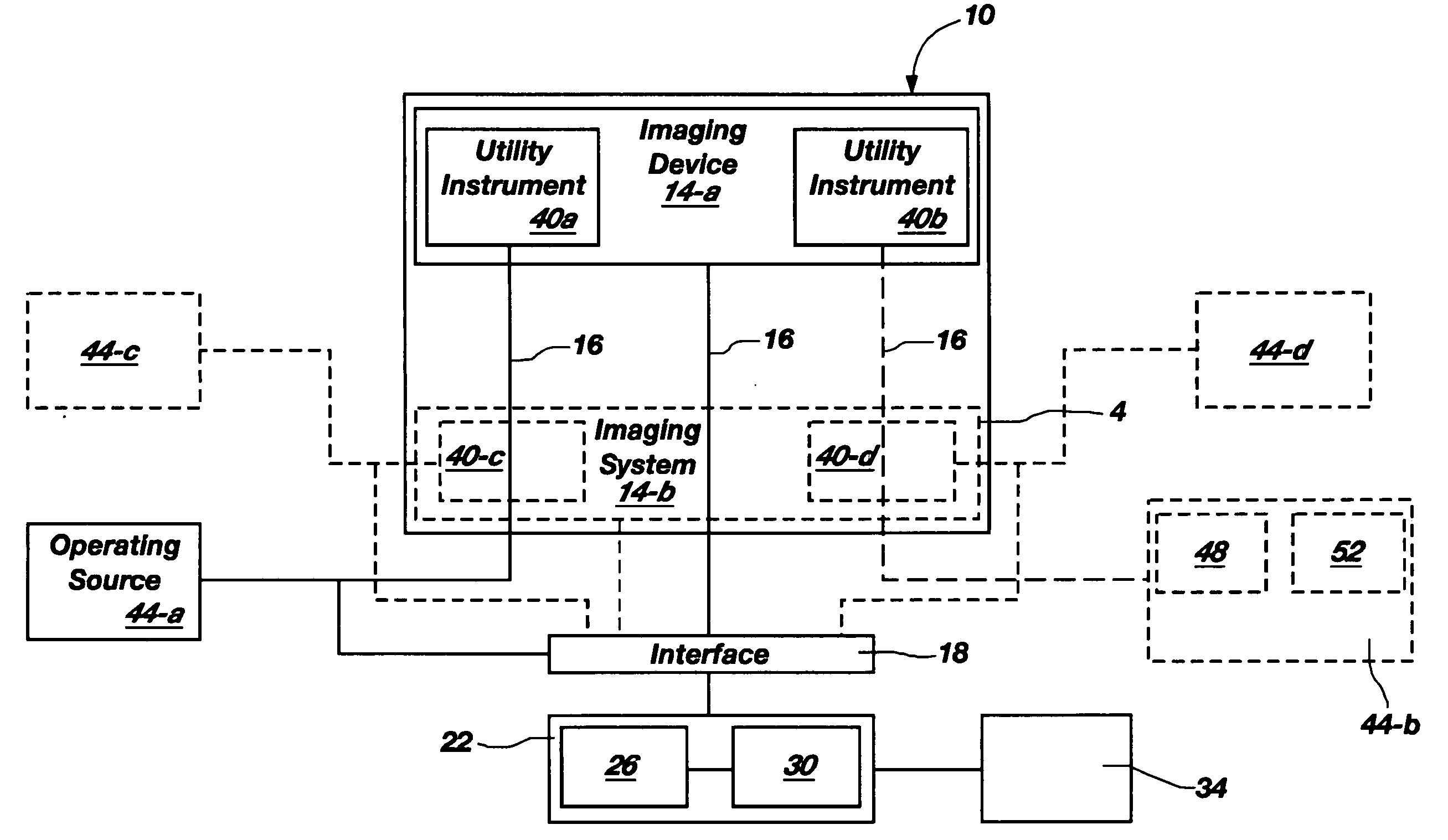
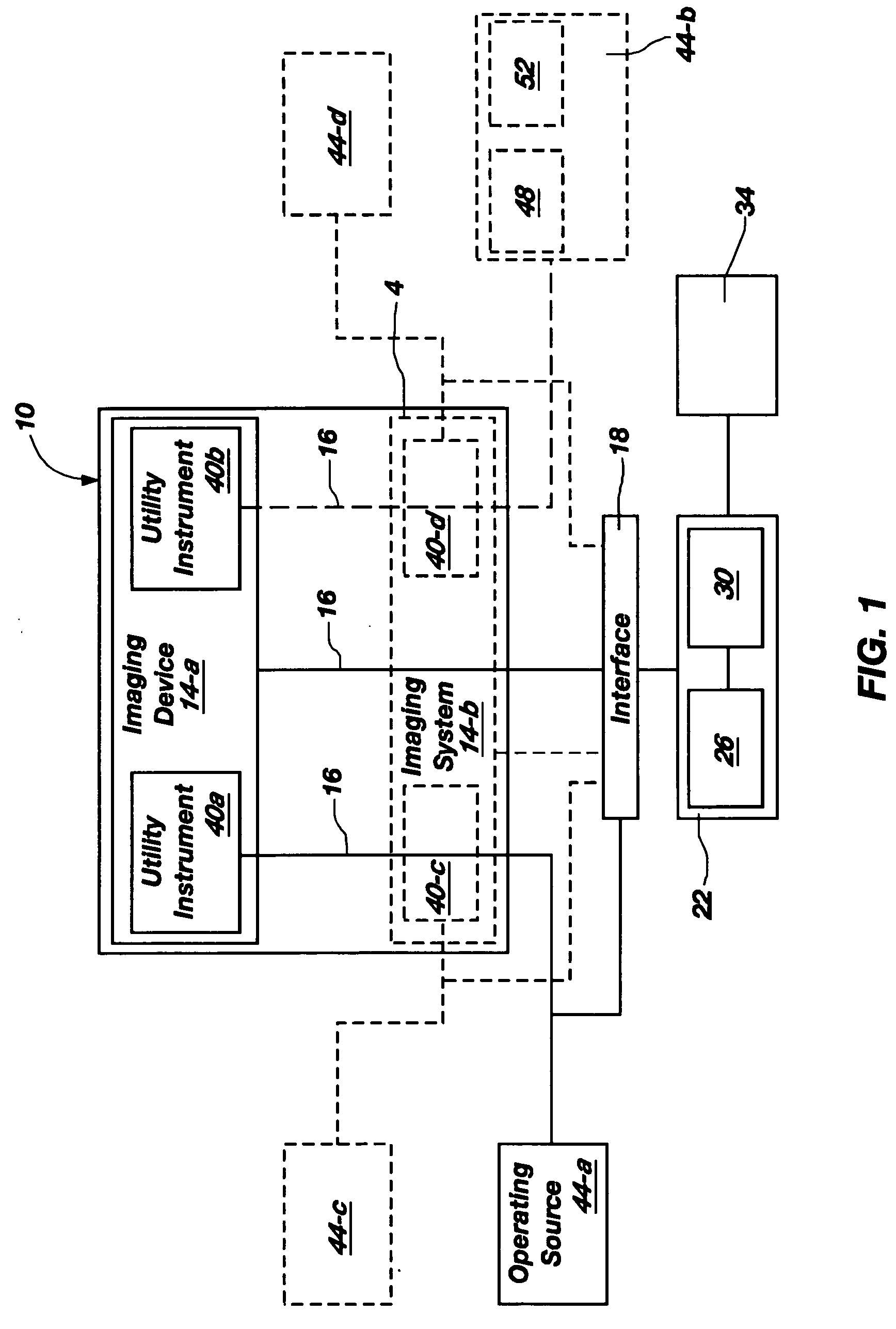
[0072]FIG. 9 illustrates a utility device 110 according one exemplary embodiment of the present invention. In this particular embodiment, utility device 110 comprises an imaging system 14 (or micro camera) as embodied and described in FIGS. 4-6, namely an SSID 84 and lens 92 combination supported on a utility guide 56 having a plurality of utility apertures 102 formed therein, and operated via conductive lines 64 (see FIGS. 4-6 for description). Although not shown, it should be noted that the utility instruments described in this Example may also be associated or used with the imaging system or micro camera as embodied and described in FIGS. 7 and 8.

[0073] Supported by utility guide 56 are utility instruments 40-a and 40-b. Specifically, utility instrument 40-a comprises a light source 76 for illuminating a local area in which a utilitarian function is to be performed or a particular object. In one aspect, as shown, light source 76 comprises a fiber optic cable 72 that is inserted ...

example two

[0079]FIG. 10 illustrates a utility device 210 according one exemplary embodiment of the present invention. In this particular embodiment, utility device 210 comprises an imaging system 14 (or micro camera) as embodied and described in FIGS. 4-6, namely an SSID 84 and lens 92 combination supported on a utility guide 56 having a plurality of utility apertures 102 formed therein, and operated via conductive lines 64 (see FIGS. 4-6 for description).

[0080] Also supported by utility guide 56 are utility instruments 40-a and 40-b. Specifically, utility instrument 40-a comprises a fluid disperser 204 inserted into and supported within a utility aperture 102 formed in the utility guide 56 of the imaging device 14 in a similar manner as previously described utility instruments. Fluid dispenser 204 includes an elongate tubular member adapted to receive and transport fluid from a fluid source to a nozzle 208 having an opening 212 therein for emitting fluid, as illustrated by the arrows. Fluid...

example three

[0084]FIG. 11 illustrates a utility device 310 according one exemplary embodiment of the present invention. In this particular embodiment, utility device 310 comprises an imaging system 14 (or micro camera) as embodied and described in FIGS. 4-6, namely an SSID 84 and lens 92 combination supported on a utility guide 56 having a plurality of utility apertures 102 formed therein, and operated via conductive lines 64 (see FIGS. 4-6 for description).

[0085] Also supported by utility guide 56 is utility instrument 40-a. Specifically, utility instrument 40-a comprises a laser 304 that is inserted into and supported by utility aperture 102 formed within the utility guide 56 of the imaging device 14. Laser 304 may comprise one of various types of lasers depending upon the particular utilitarian function to be performed. For example, in the performance of an ablation function, the laser may be an excimer-type or other similar laser that enables the disintegration of targeted tissue without s...


PUM


Abstract

A miniaturized utility device having integrated optical capabilities for use on a high aspect ratio system, wherein the miniaturized utility device comprises: (a) a micro camera comprising a solid state micro imaging device including, as an integral structure, an imaging array electrically coupled to a conductive pad, wherein the solid state imaging device further includes at least one utility aperture passing therethrough, and a lens optically coupled to the imaging array; and (b) a micro utility instrument configured for coordinated operation with the imaging device at a common local site, wherein the micro utility instrument is configured to perform a designated function viewable, preferably in real-time, via a camera image generated by the micro camera.

Description

RELATED APPLICATIONS [0001] This continuation in-part application claims priority to U.S. Provisional Patent Application No. 60 / 632,827, filed Dec. 2, 2004 in the United States Patent and Trademark Office, and entitled, “Miniaturized Utility Device Having Integrated Optical Capabilities” which application is incorporated by reference in its entirety herein. This a continuation-in-part application also claims priority to U.S. patent application Ser. Nos. 10 / 391,513, 10 / 391,490, and 10 / 391,489, each filed Mar. 17, 2003, and each of which claim priority to U.S. Provisional Patent Application Nos. 60 / 431,261, filed Dec. 6, 2002; 60 / 365,561, filed Mar. 18, 2002; and 60 / 365,692 filed Mar. 18, 2002, each of which are incorporated by reference in their entirety herein.FIELD OF THE INVENTION [0002] The present invention relates to miniaturized imaging devices that are particularly suited to viewing beyond small openings and traversing small-diameter areas, and more particularly to miniaturiz...

Claims


Application Information

Patent Timeline
Patent Type & Authority Applications(United States)
IPC IPC(8): H04N5/225
CPCA61B1/018A61B1/05A61B1/051A61B1/053A61B1/12H04N5/2251H04N5/2252H04N5/2256H04N2005/2255H04N23/555H04N23/56H04N23/51H04N23/50
Inventor JACOBSEN, STEPHEN C.MARKUS, DAVID T.MARCEAU, DAVID P.PENSEL, RALPH W.ZURN, SHAYNE M.
Owner STERLING L C
Learn More