Diffractive optical element, objective lens module, optical pickup, and optical information recording and reproducing apparatus

a technology of optical elements and pickups, applied in the field of optical elements, can solve the problems of disadvantageous reducing the size of the apparatus, affecting the performance of the apparatus, and affecting the compatibility of three or more kinds of recording media having different light source wavelengths, so as to improve the efficiency of the apparatus, prevent trouble, and simplify the optical path of the pickup

Inactive Publication Date: 2006-07-06
PIONEER CORP
View PDF1 Cites 108 Cited by
  • Summary
  • Abstract
  • Description
  • Claims
  • Application Information

AI Technical Summary

Benefits of technology

[0010] Accordingly, it is an object of the present invention to provide an optical information recording and reproducing apparatus which is capable of recording and reproducing for optical discs or recording surfaces having different correspondingwavelengths and is suitable for reducing the size, an optical pickup device, and a diffractive optical element.
[0017] In such a configuration of the objective lens module or the pickup in which the diffractive optical element is used, with the study for the diffractive optical element, BD, DVD, and CD can be designed as an infinite system, such that an optical path of the pickup can be simplified.
[0018] At the time of BD / DVD / CD compatible, a diffractive lens structure for chromatic aberration correction may be added to a diffractive optical element for spherical aberration correction, and thus a discontinuous chromatic aberration can be corrected.
[0019] The diffractive lens structure for spherical aberration correction and the diffractive lens structure for chromatic aberration correction may be integrated. Therefore, it is possible to prevent a trouble in correcting a discontinuous chromatic aberration correction due to an adjustment error at the time of assembling or a lens shift caused by tracking.

Problems solved by technology

That is, it is difficult to realize compatibility of three or more kinds of recording mediums having different light source wavelengths, numerical apertures (effective diameters), optical disc thicknesses (the thickness of a transmissive protection layer), such as BD, DVD, CD, and the like by use of a single objective lens according to the related art.
In this case, however, since two objective lenses are used, a complex lens switching mechanism needs to be provided, which causes a problem in that manufacturing costs are increased.
In addition, since an actuator is made large, it is disadvantageous to reduce the size of the apparatus.
Further, a method may be considered in which an objective lens and a collimator lens are incorporated, but, since the collimator is fixedwith respect to the objective lens, it may be difficult to maintain performance at the time of movement of the objective lens.
In any cases, if a plurality of light sources are used, and an optical system of exclusive prism, lens, and the like is configured in order to ensure compatibility of BD, DVD, and CD, an optical pickup or an overall optical head is complicated, and tends to have the large size.

Method used


Image

  • Diffractive optical element, objective lens module, optical pickup, and optical information recording and reproducing apparatus
  • Diffractive optical element, objective lens module, optical pickup, and optical information recording and reproducing apparatus
  • Diffractive optical element, objective lens module, optical pickup, and optical information recording and reproducing apparatus

Examples


example 1

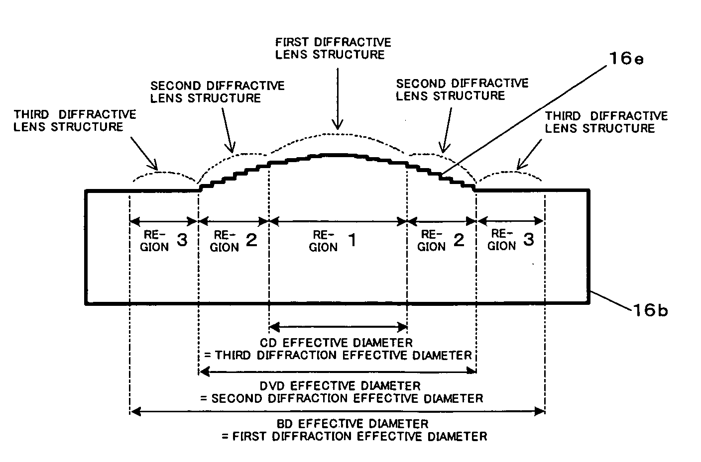
[0330] In general, a diffractive lens structure used for the optical disc has a plurality of concentric minute phase steps, and controls the wavefront of light by use of diffraction of light by the phase steps. As a method of designing such a diffractive lens structure, the phase function method is used. In the phase function method, an infinitely thin phase object is assumed on a surface where the diffractive lens structure is formed, and the aberration is calculated by adding the phase, which is given through a phase function ψ(h) represented by the following equation, with respect to a light beam passing through the distance (height) h from the optical axis. Here, dor is a diffraction order, and λ0 is a designed wavelength. ψ⁡(h)=dor⁢2⁢ ⁢πλ0⁢∑i⁢di·hi

[0331] Here, the phase function ψ(h) is arranged as the following equation, and Δ(h) is referred to as a diffractive lens function. Ψ⁡(h)=dor·2⁢ ⁢π·Δ⁡(h)Δ⁡(h)=1λ0⁢∑i⁢di·hi

[0332] The height from the optical axis of each of the plural...

example 2

[0400] Example 2 is also, like Example 1, a diffractive optical element that can record on and reproduce BD, the first optical data storage media; DVD, the second optical data storage media; and CD, the third optical data storage media; and combined with a double aspherical lens for BD. In addition, Example 2 is designed in consideration of the effect of chromatic aberration arising from slight wavelength variation of a light source.

[0401] In general, the wavelength of a light source such as a semiconductor laser that is used for an optical disc can be varied by temperature variation or power variation generated during recording and reproducing. As a result, the focal length of an objective lens varies, and spherical aberration occurs. The amount of wavefront aberration of the chromatic aberration arising from the wavelength variation increases with the numerical aperture of a lens. If the wavelength is varied rapidly with operating variation such as recording to reproducing or rep...

example 3

[0447] Example 3 is also, like Example 2, a diffractive optical element that can record on and reproduce BD, DVD and CD. In addition, the diffractive optical element of Example 3 is designed in consideration of the effect of the chromatic aberration due to the slight wavelength variation of the light source.

[0448] Table 23 illustrates the composition of the lens system and the design conditions for BD, DVD and CD in Example 3.

TABLE 23BDDVDCDLight source wavelength [nm]408660780Magnification000Numeric aperture0.850.650.50Effective diameter [mm]4.0003.2462.540Disc thickness [mm]0.10.61.2

[0449] In Example 2, the diffractive lens structures are formed on both surfaces of the diffractive optical element. However, in this case, since the diffractive lens structures are formed at both surfaces of the element, two high-precision molds including finephase steps are required, and thus the cost rises. Therefore, in Example 3, all diffractive lens structures are formed at a single surface as...


PUM


Abstract

An objective lens module includes a light-converging lens that is coaxially disposed with respect to an optical axis of first laser light having a first wavelength, and a transmission-type diffractive optical element that is coaxially disposed to cause diffracted light of first laser light to be incident on the light-converging lens. The diffractive optical element has an incident surface and an emergent surface, and first, second, and third regions that are provided on at least of the incident surface and the emergent surface inthe vicinity of the optical axis, and are sequentially defined according to different radius distances from the optical axis to have different diffraction gratings of different diffraction angles, respectively. The first region diffracts odd-order diffracted light of first laser light to the light-converging lens, the second region diffracts even-order diffracted light of first laser light to the light-converging lens, and the third region diffracts even-order or zero-order diffracted light of first laser light to the light-converging lens, such that the light-converging lens converges diffracted light from the first, second, and third regions with a predetermined numerical aperture.

Description

BACKGROUND OF THE INVENTION [0001] 1. Field of the Invention [0002] The present invention relates to an optical system of an optical pickup in an optical information recording and reproducing apparatus which records and reproduces information for optical discs having different corresponding wavelengths. More particularly, the present invention relates to an optical information recording and reproducing apparatus which allows compatibility for a plurality of optical recording mediums using laser light sources of different wavelengths, to an optical pickup, to an objective lens module, and to a diffractive optical element. [0003] 2. Description of Related Art [0004] As an optical information recording and reproducing apparatus, an optical disc apparatus is known in which recorded information can be read from an optical recording medium, that is, an optical disc, such as digitalversatile disc (hereinafter, referred to as DVD), compact disc (hereinafter, referred to as CD), or the like....

Claims


Application Information

Patent Timeline
Patent Type & Authority Applications(United States)
IPC IPC(8): G02B3/08
CPCG02B5/188G02B27/0037G02B27/4238G11B7/1275G11B7/1353G11B7/1374G11B7/13922G11B2007/0006G11B2007/13727
Inventor KOIKE, KATSUHIRO
Owner PIONEER CORP
Why Eureka
Try Eureka