Adaptive equalization with group delay

a group delay and equalization technology, applied in the field of adaptive equalization with group delay, can solve the problems of group delay distortion, frequency-related attenuation, noise and bandwidth limitations of typical optical networks, etc., and achieve the effect of reducing undesired interactions

Inactive Publication Date: 2006-07-06
MICROSEMI STORAGE SOLUTIONS
View PDF9 Cites 36 Cited by
  • Summary
  • Abstract
  • Description
  • Claims
  • Application Information

AI Technical Summary

Benefits of technology

[0011] The present invention relates to methods, apparatuses, and systems for performing adaptive equalization involving receiving a signal originating from a channel associated with inter-symbol interference, filtering the received signal using a filter having a plurality of adjustable tap weights to produce a filtered signal, and adaptively updating each of the plurality of adjustable tap weights to a new value to reduce effects of inter-symbol interference, wherein each of the plurality of adjustable tap weights is adaptively updated to take into account a constraint relating to a measure of error in the filtered signal and a constraint relating to group delay associated with the filter.
[0013] According to one embodiment of the invention, the filter is part of an adaptive equalizer, the adaptive equalizer is coupled to a clock recovery phase lock loop, and group delay associated with the filter reduces undesired interaction between the equalizer and the clock recovery phase lock loop. In one embodiment, the filter is part of an adaptive equalizer, and the adaptive equalizer is a decision-feedback equalizer (DFE). Further, in one embodiment, each of the plurality of adjustable tap weights is adaptively updated to take into account the constraint relating to the measure of error in the filtered signal, based on a least-mean-square (LMS) algorithm.

Problems solved by technology

Typical optical networks are plagued by noise and bandwidth limitations caused by polarization mode dispersion, modal dispersion, chromatic dispersion, limited component bandwidth, and / or other undesired phenomena.
Such effects often cause problems such as group delay distortion, frequency-related attenuation, and / or others.
However, the implementation of such devices has proven to be challenging and costly.
One particularly difficult problem in the design of optical receivers relates to mutual interference that may exist between an adaptive equalizer and other circuit(s). FIG. 1 is a block diagram of a typical optical receiver 100 capable of receiving signals from an optical communication channel.
Such interference can be associated with instability affecting one or more components of optical receiver 100 and can lead to dramatic performance degradations.
Despite these and other desirable properties, the arrangement shown in FIG. 2 is prone to interference that may exist between portions of the adaptive equalizer and portions of the clock recovery circuit.
Such dynamic operations interfere with one another, and this mutual interference may cause instability in one, some, or all of the operations involved.

Method used


Image

  • Adaptive equalization with group delay
  • Adaptive equalization with group delay
  • Adaptive equalization with group delay

Examples


Embodiment Construction

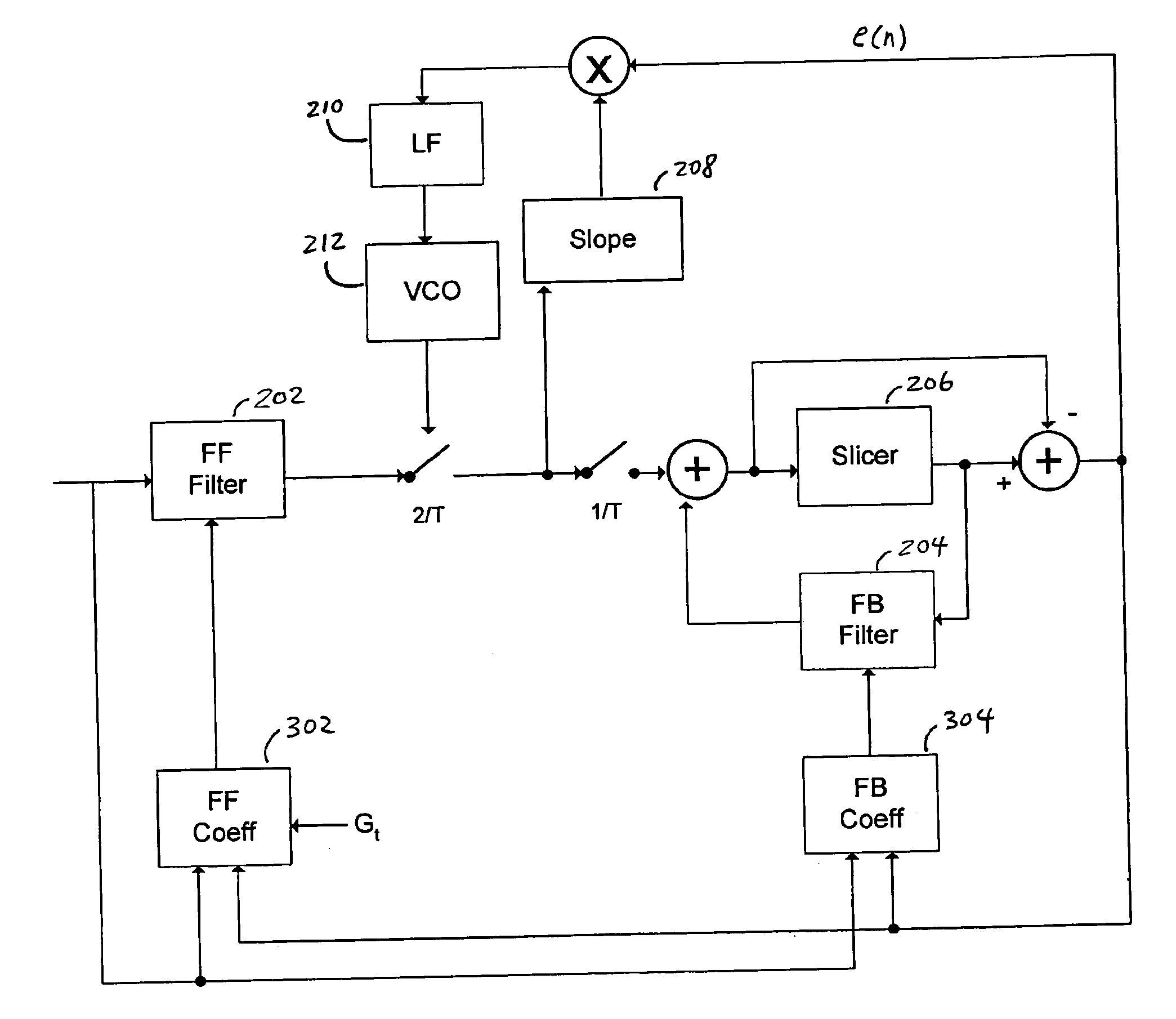
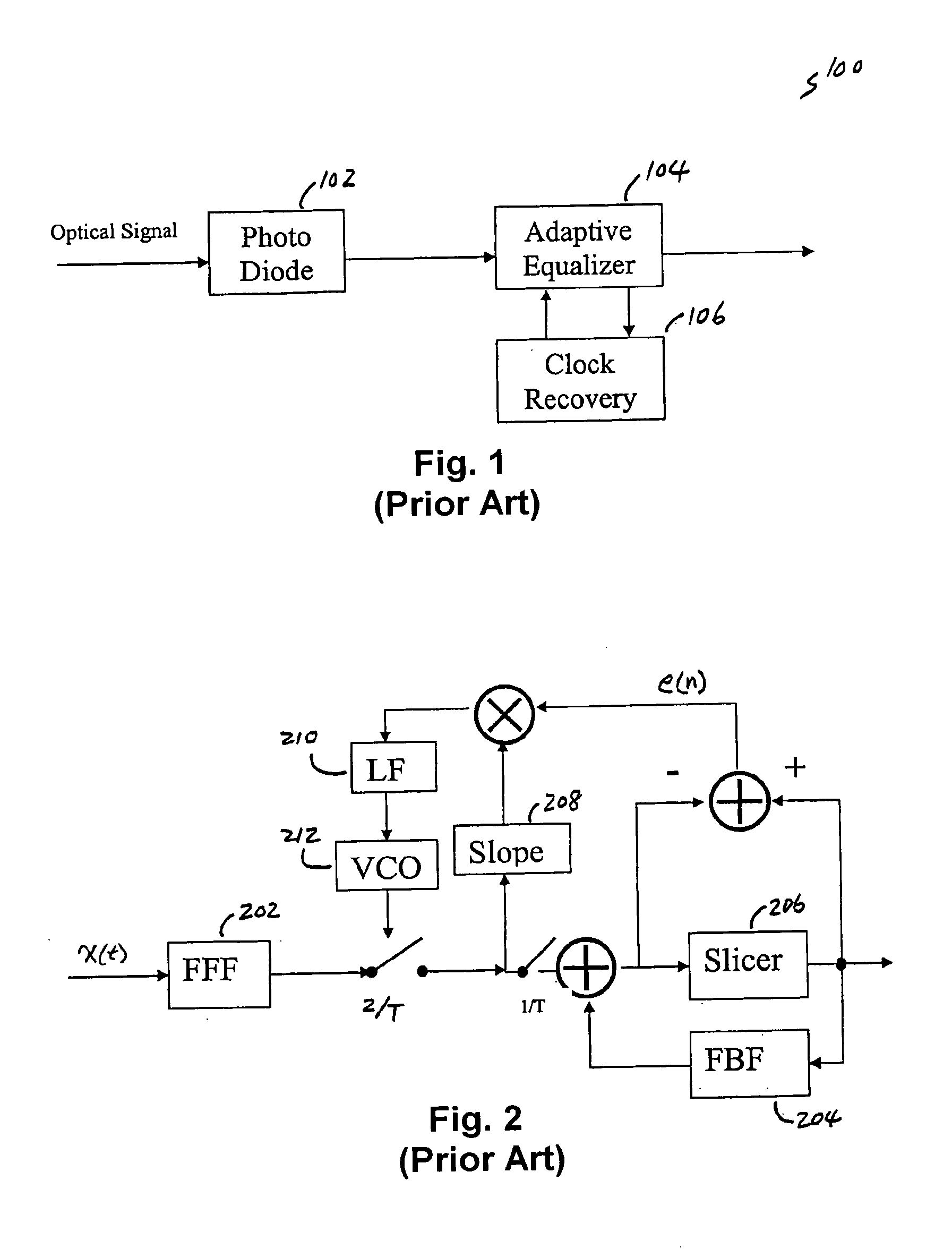
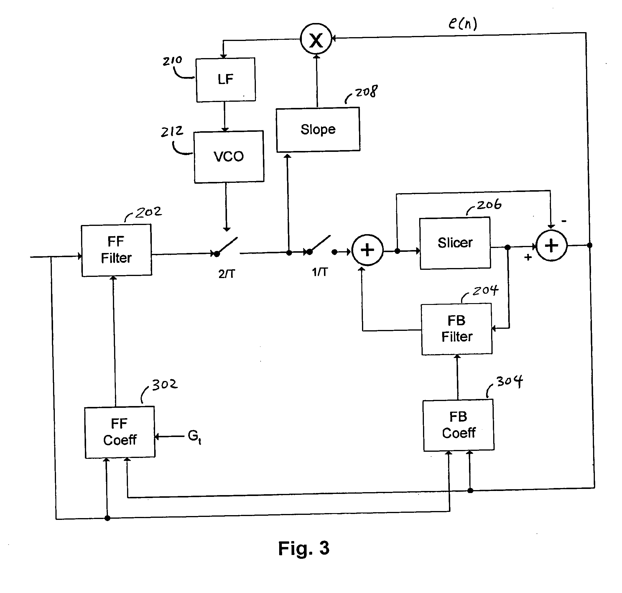
[0023]FIG. 3 is a block diagram of a portion of a receiver containing an adaptive equalizer coupled to a clock recovery circuit that minimizes mean square error (MMSE), wherein the adaptive equalizer takes into account filter group delay to reduce mutual interference with the clock recovery circuit, in accordance with one embodiment of the present invention. As previously illustrated in FIG. 2, the adaptive equalizer is a decision-feedback equalizer (DFE) that utilizes both feed-forward filter 202 and feed-back filter 204, as well as slicer 206. The clock recovery circuit utilizes slope estimator 208, low-pass filter 210, VCO 212, and slicer 206. A feed-forward coefficient unit 302 automatically adjusts the coefficients, or taps, of feed-forward filter 202 in order to optimize one or more performance measures. Here, feed-forward coefficient unit 302 updates the coefficients of feed-forward filter 202 using an approach based on the least-mean-square (LMS) algorithm. Thus, for each ta...


PUM


Abstract

Methods, apparatuses, and systems are presented for performing adaptive equalization involving receiving a signal originating from a channel associated with inter-symbol interference, filtering the signal using a filter having a plurality of adjustable tap weights to produce a filtered signal, and adaptively updating each of the plurality of adjustable tap weights to a new value to reduce effects of inter-symbol interference, wherein each of the plurality of adjustable tap weights is adaptively updated to take into account a constraint relating to a measure of error in the filtered signal and a constraint relating to group delay associated with the filter. Each of the plurality of adjustable tap weights may be adaptively updated to drive group delay associated with the filter toward a target group delay.

Description

CROSS-REFERENCES TO RELATED APPLICATIONS [0001] This application is related to U.S. patent application Ser. No. 10 / 872,108, filed Jun. 17, 2004 by Shanthi Pavan for “Power and Area Efficient Adaptive Equalization” (Attorney Docket No. 021795-000500US), the entire disclosure of which is incorporated by reference in this application for all purposes. [0002] This application is also related to U.S. patent application Ser. No. 10 / 872,307, filed Jun. 17. 2004 by Shanthi Pavan for “Improved Integrated Circuit Implementation for Power and Area Efficient Adaptive Equalization” (Attorney Docket No. 021795-000600US), the entire disclosure of which is incorporated by reference in this application for all purposes.BACKGROUND OF THE INVENTION [0003] Increased demand for high-speed communications services has required that economical and efficient new devices and techniques be developed to support performance increases. For example, as transmission rates climb to the 10-40 Gbps range and beyond i...

Claims


Application Information

Patent Timeline
Patent Type & Authority Applications(United States)
IPC IPC(8): H03H7/30
CPCH03H15/00H03H21/0012H04L7/0062H04L12/66H04L25/03057H04L2025/0349H04L2025/03509H04L2025/03681
Inventor BHOJA, SUDEEPWANG, JOHN S.TAO, HAI
Owner MICROSEMI STORAGE SOLUTIONS
Why Eureka
Try Eureka