
Eureka
For R&D, Eureka makes reading and utilizing patents & technical documents easy.
Eureka AIR
Designed for self-driven R&D workflows. Generate viable solutions, solve complex R&D challenges, empower your innovation with AI.

Eureka Materials
Designed for material experts only. Revolutionize your material R&D, from search, analyze, to developing new materials.

TechResearch
Generate reliable direction feasibility study reports for your R&D in just a few steps.

TechSeek
Discover and master advanced knowledge NOW. Basics, ideas, possibilities, all at once.

TechMind
As an expert in R&D Theories, TechMind can generates customized viable solutions instantly.

TechRisk
Analyze your overall solution with one click, know your potential R&D risks in advance.

TechMonitor
Get weekly tech updates, stay abreast of the latest tech innovations and key insights.
Internal combustion engine control apparatus
- Summary
- Abstract
- Description
- Claims
- Application Information
AI Technical Summary
Benefits of technology
Problems solved by technology
Method used
Image

Examples
first embodiment
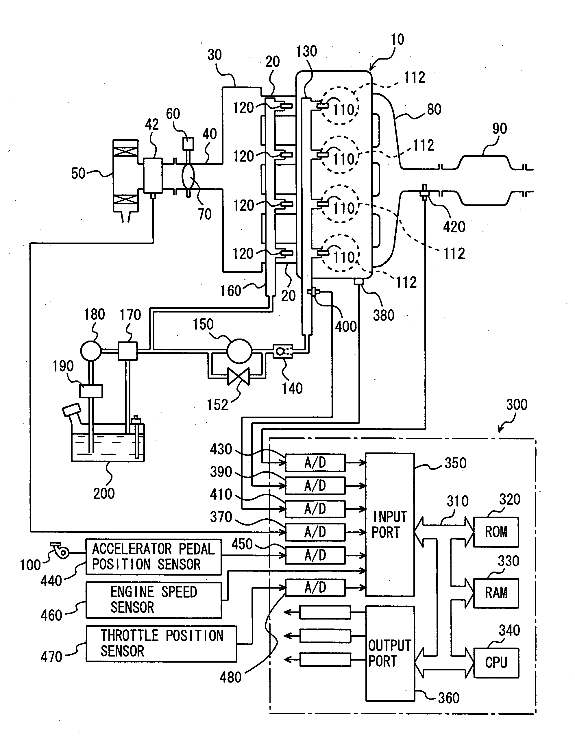
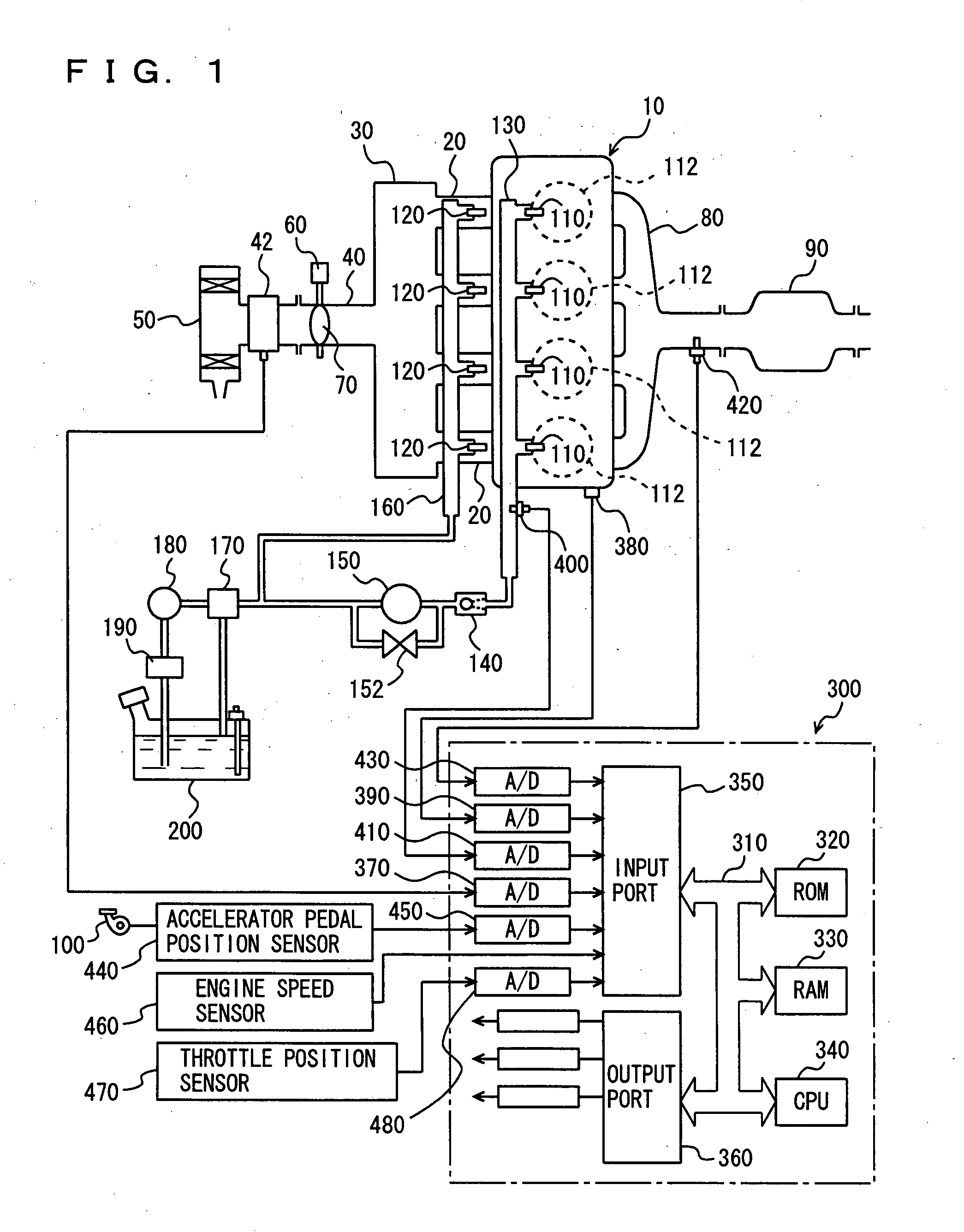
[0047]FIG. 1 is a schematic configuration diagram of an engine system that is controlled by an engine ECU (Electronic Control Unit) implementing the control apparatus for an internal combustion engine according to a first embodiment of the present invention. In FIG. 1, an in-line 4-cylinder gasoline engine is shown, although the application of the present invention is not restricted to such an engine.
[0048] As shown in FIG. 1, the engine 10 includes four cylinders 112, each connected via a corresponding intake manifold 20 to a common surge tank 30. Surge tank 30 is connected via an intake duct 40 to an air cleaner 50. An airflow meter 42 is arranged in intake duct 40, and a throttle valve 70 driven by an electric motor 60 is also arranged in intake duct 40. Throttle valve 70 has its angle controlled in degree as based on a signal output from an engine ECU 300, independently from an accelerator pedal 100. Each cylinder 112 is connected to a common exhaust manifold 80, which is conne...
second embodiment
[0079] With reference to FIG. 11 the present invention in a second embodiment will be described. In the first embodiment a deposit is cleared, as controlled, and thus removed. In the present embodiment, in addition to clearing a deposit, as controlled, the intake manifold injector provides injection in an increased amount. The remainder is identical to that of the first embodiment. It is also identical in function.
[0080] With reference to FIG. 11, the present embodiment provides a control apparatus or engine ECU 300 executing a program having a configuration for control, as described hereinafter. Any steps identical to those of the program described in the first embodiment are identically labeled.
[0081] At S200 engine ECU 300 increments a counter C by one. By counter C engine ECU 300 indirectly counts a period of time having elapsed since a deposit was cleared, as controlled.
[0082] At S202 engine ECU 300 determines whether counter C is larger than a predetermined value C(0) to de...
third embodiment
[0091] With reference to FIG. 12 the present invention in a third embodiment will be described. In the first embodiment a deposit is cleared, as controlled, and thus removed. In the present embodiment, in addition to clearing a deposit, as controlled, the intake manifold injector provides injection in an increased amount. The remainder is identical to that of the first embodiment. It is also identical in function.
[0092] With reference to FIG. 12, the present embodiment provides a control apparatus or engine ECU 300 executing a program having a configuration for control, as described hereinafter. Any steps identical to those of the program described in the first embodiment are identically labeled.
[0093] At S300 engine ECU 300 determines whether the estimated amount of intake air GAINI minus the detected amount of intake air GA is larger than a predetermined deviation ΔGA(1). If so (YES at S300) the process proceeds to S302. Otherwise (NO at S300) the process proceeds to S108.
[0094...
PUM
 Abstract
Description
Claims
Application Information
 - R&D Engineer
- R&D Manager
- IP Professional
- Industry Leading Data Capabilities
- Powerful AI technology
- Patent DNA Extraction
Browse by: Latest US Patents, China's latest patents, Technical Efficacy Thesaurus, Application Domain, Technology Topic, Popular Technical Reports.
© 2024 PatSnap. All rights reserved.Legal|Privacy policy|Modern Slavery Act Transparency Statement|Sitemap|About US| Contact US: help@patsnap.com