Performance of a receiver in interfering conditions

Inactive Publication Date: 2006-07-13
NOKIA TECHNOLOGLES OY
View PDF12 Cites 28 Cited by
  • Summary
  • Abstract
  • Description
  • Claims
  • Application Information

AI Technical Summary

Benefits of technology

[0031] It is an advantage of the invention that it provides an alternative to existing solutions.
[0032] When detuning the antenna, also the received signal is attenuated. If the received signal is weak, the attenuation causes that the signal cannot be detected. However, if the signal is strong, it may be possible to detect the signal in spite of the attenuation. This constitutes an advantage compared to the solution proposed in the above cited document U.S. Pat. No. 6,107,960, as here, the blocking or disregarding of satellite signals affects satellite signals of any strength.
[0033] It is further an advantage of the invention that it requires no additional components in a communication system transmitter of the device.
[0034] Preferred embodiments of the invention become apparent from the dependent claims.
[0035] The invention can be employed in any device comprising a receiver. The receiver can be for example a satellite positioning system receiver like a GPS receiver or a Galileo receiver, but equally any other type of receiver. The invention can b

Problems solved by technology

Moreover, the proposed device comprises a controlling portion causing the tuning component to shift the frequency response of the a

Method used


Image

  • Performance of a receiver in interfering conditions
  • Performance of a receiver in interfering conditions
  • Performance of a receiver in interfering conditions

Examples


first embodiment

[0050]FIG. 2 is a schematic block diagram of a mobile phone 20, in which the invention is implemented. Only selected components of the mobile phone 20 are depicted.

[0051] The mobile phone supports a GPS positioning and a mobile communication via a GSM network.

[0052] For supporting the GPS positioning, the mobile phone 20 comprises a GPS receiver 21. The GPS receiver 21 includes, connected to each other in series, a low noise amplifier LNA 211, a mixer 212, a variable gain attenuator 213 and a converters and DSP (digital signal processor) processor block 214. A local oscillator 215 is connected in addition to the mixer 212. The local oscillator 215 provides a signal having a frequency required for downconverting an L1 signal. The mobile phone 20 further comprises a GPS antenna 216 which is connected via a tuning component 217 to the low noise amplifier 211 of the GPS receiver 21. The tuning component 217 comprises a detuning circuitry, e.g. a capacitance diode, for tuning the freque...

third embodiment

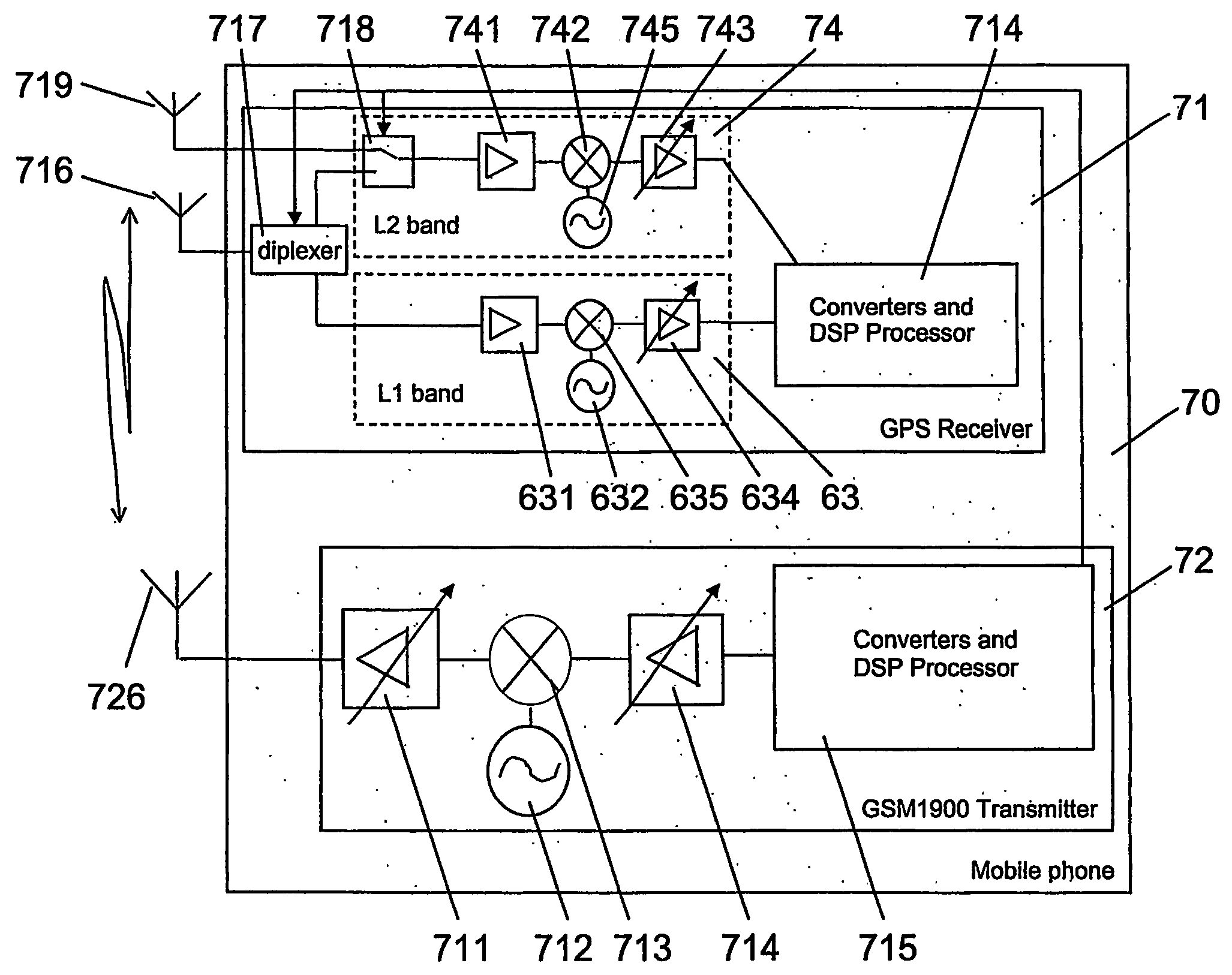
[0062] A second and the invention, which will be presented further below, take into account planned future developments of GPS.

second embodiment

[0063] the invention is based on the assumption that in addition to the C / A-code of the L1 signal, also the P-code of the L1 signal and the L2 signal including a C / A code and a P-code are taken into civil usage.

[0064]FIG. 4 is a schematic block diagram of a mobile phone 40, in which the second embodiment of the invention is implemented. As in FIG. 2, only selected components of the mobile phone 40 are depicted.

[0065] The mobile phone 40 of FIG. 4 supports again a GPS positioning and a mobile communication via a GSM network. For supporting a GPS positioning, the mobile phone 40 of FIG. 4 comprises a GPS receiver 41. The GPS receiver 41 includes a first receiving chain 43 for receiving and processing L1 signals and a second receiving chain 44 for receiving and processing L2 signals. The L1 receiving chain 43 comprises, connected to each other in series, a first low noise amplifier LNA 431, a first mixer 432 and a first variable gain attenuator 433. The L1 receiving chain 43 further c...


PUM


Abstract

A device 20 includes a receiver 21 for receiving and processing signals at least in a first frequency band and an antenna 216 which is connected to the receiver 21. In order to improve the performance of such a receiver, the device 20 in addition includes a tuning component 217 for shifting a frequency response of the antenna 216 from the first frequency band to a second frequency band. Further, the device 20 includes a controlling portion 221 causing the tuning component 217 to shift the frequency response of the antenna 216 from the first frequency band to the second frequency band, in case a wideband noise is expected in the first frequency band. A corresponding method is shown as well.

Description

FIELD OF THE INVENTION [0001] The invention relates to a device comprising a receiver for receiving and processing signals and an antenna which is connected to the receiver. The invention relates equally to a method for improving the performance of such a receiver. BACKGROUND OF THE INVENTION [0002] Receivers for receiving and processing signals are well known in the art, for example in form of a GPS (Global Positioning System) receiver of a GPS system. [0003] The performance of a receiver may be degraded during time intervals in which wideband noise in the frequency band used for the signals which are to be received by the receiver is present in the environment of the device, since this wideband noise may reduce the signal-to-noise ratio (SNR) of the received signals significantly. [0004] The wideband noise can be generated in particular by a communication system transmitter integrated in the same device as the receiver, or by a nearby communication system transmitter external to t...

Claims


Application Information

Patent Timeline
IPC IPC(8): G01S5/14H04M1/00G01S1/00G01S19/21G01S19/32G01S19/36H04B1/14H04B1/38
CPCG01S19/21G01S19/32G01S19/36H04B1/1027H04B1/3805
Inventor LEINONEN, MARKOROUSU, SEPPO
Owner NOKIA TECHNOLOGLES OY
Why Eureka
Try Eureka