Cooling system including mini channels within a turbine blade of a turbine engine

a cooling system and turbine blade technology, applied in the direction of machines/engines, liquid fuel engines, mechanical equipment, etc., can solve the problems of reducing the useful life of the turbine blade, the likelihood of failure, and localized hot spots, so as to increase the convective surface area, enhance the overall cooling effect of the cooling system, and increase the convective coefficient

Inactive Publication Date: 2006-07-13
SIEMENS ENERGY INC
View PDF16 Cites 26 Cited by
  • Summary
  • Abstract
  • Description
  • Claims
  • Application Information

AI Technical Summary

Benefits of technology

[0012] Yet another advantage of this invention is that the ribs forming the first and second passageways increase the convection coefficients by increasing the velocity of the cooling fluid flow and are constructed with a length that prevents formation of a fully developed boundary layer.
[0013] Another advantage of this invention is that the second passageway is positioned a distance downstream of the first passageway such that the cooling fluids emitted from the first passageway impinge on the second ribs forming the second passageway and vice versa when the pattern is repeated downstream.
[0014] Still another advantage of this invention is that the ribs increase the convective surface area in the cooling system, thereby enhancing the overall cooling effectiveness of the co...

Problems solved by technology

In addition, turbine blades often contain cooling systems for prolonging the life of the blades and reducing the likelihood of failure as a result of excessive temperatures.
However, centrifugal forces and air flow at boundary layers often prevent some areas of the turbine blade from being adequately cooled, which results in the formation of localized hot spots.
Localized hot spots, depending on their location, can reduce the useful life of...

Method used


Image

  • Cooling system including mini channels within a turbine blade of a turbine engine
  • Cooling system including mini channels within a turbine blade of a turbine engine
  • Cooling system including mini channels within a turbine blade of a turbine engine

Examples


Embodiment Construction

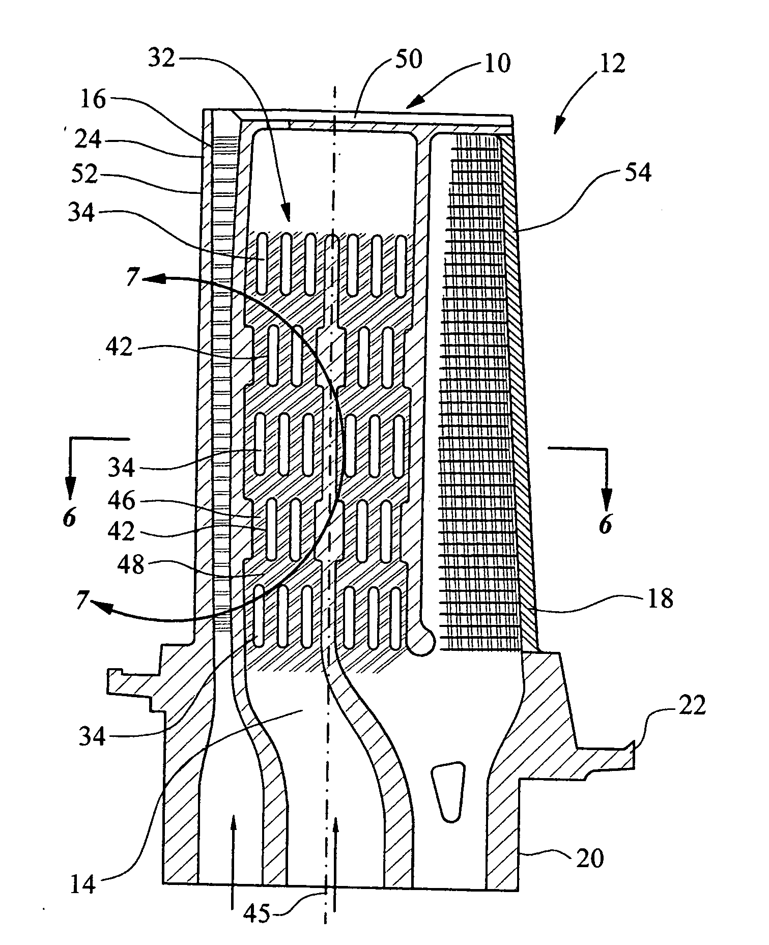
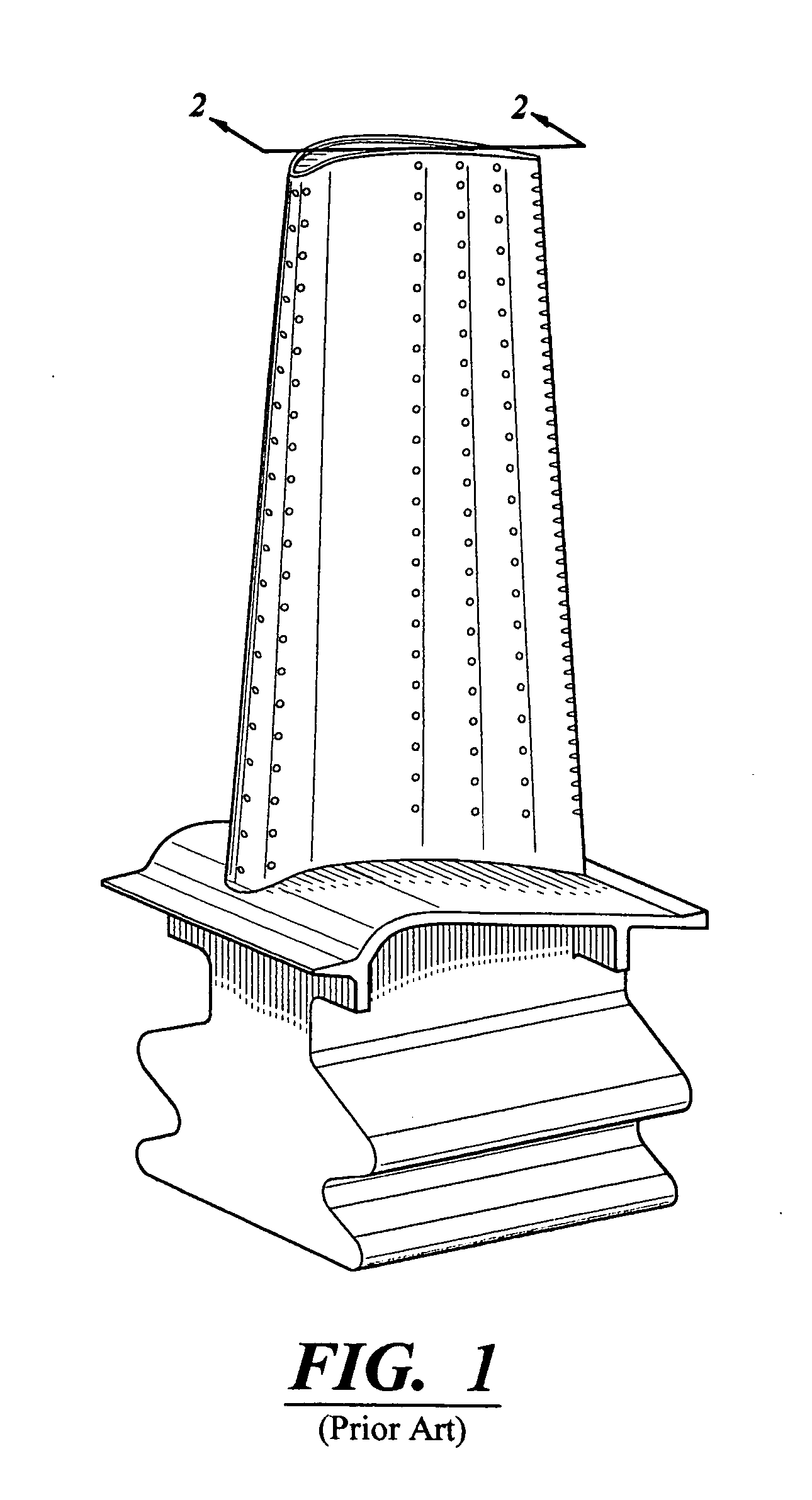
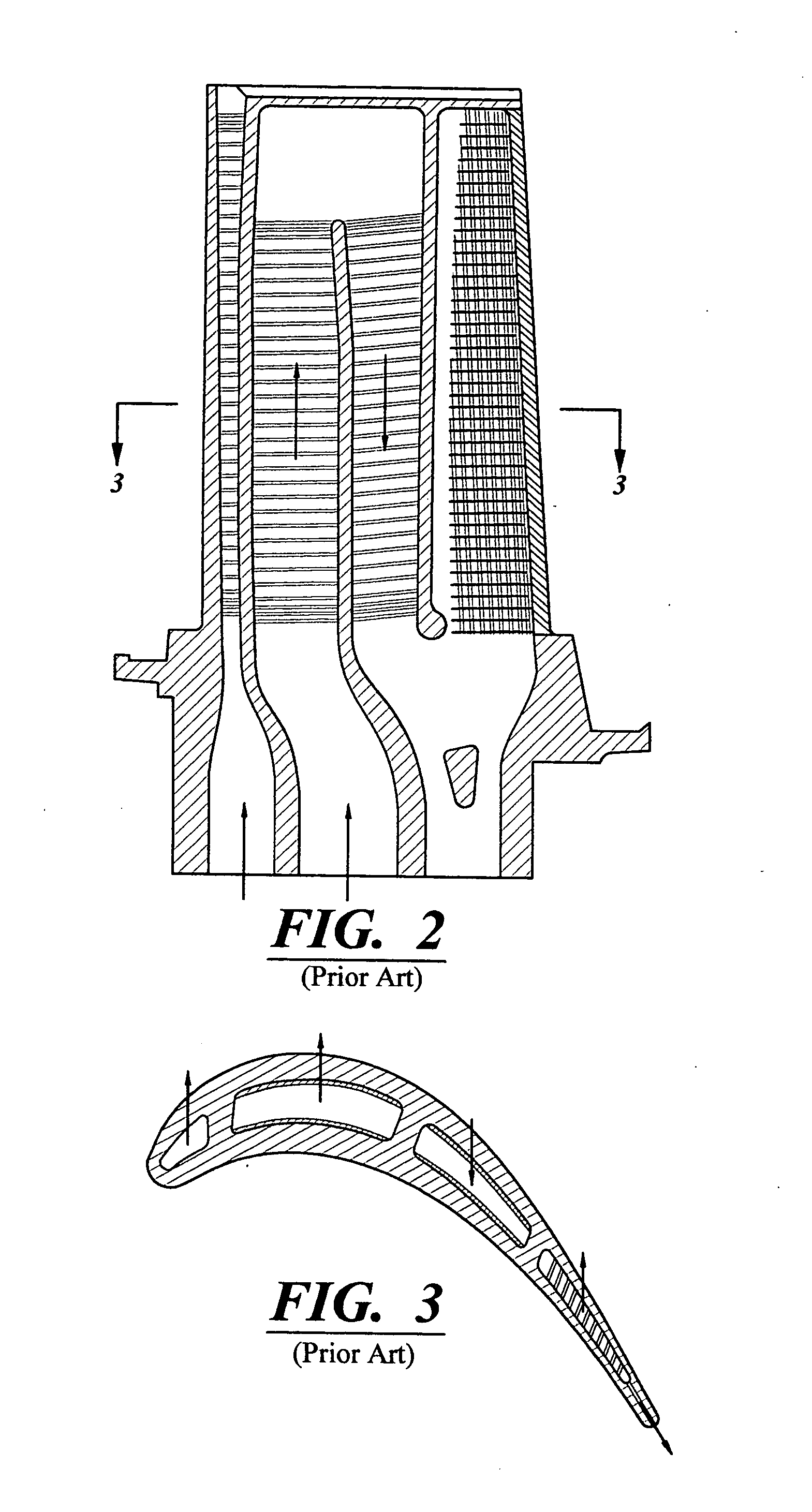
[0028] As shown in FIGS. 4-8, this invention is directed to a turbine blade cooling system 10 for turbine blades 12 used in turbine engines. In particular, the turbine blade cooling system 10 is directed to a cooling system 10 formed at least from a cooling channel 14, as shown in FIG. 5, positioned between two or more walls forming a housing 16 of the turbine blade 12. As shown in FIG. 4, the turbine blade 12 may be formed from a generally elongated blade 18 coupled to the root 20 at the platform 22. Blade 18 may have an outer wall 24 adapted for use, for example, in a first stage of an axial flow turbine engine. Outer wall 24 may have a generally concave shaped portion forming pressure side 26 and a generally convex shaped portion forming suction side 28.

[0029] The channel 14, as shown in FIG. 5, may be positioned in inner aspects of the blade 20 for directing one or more gases, which may include air received from a compressor (not shown), through the blade 18 and out one or more...


PUM


Abstract

A turbine blade for a turbine engine having a cooling system formed from one or more cooling channels having a plurality of mini channels. The cooling system may include first ribs forming a first passageway of mini channels in which the cross-sectional area of the cooling channel is reduced, thereby increasing the velocity of the cooling fluids and the internal heat transfer coefficient. The cooling system may also include second ribs forming a second passageway downstream from the first passageway a distance sufficient to prevent the formation of a fully developed boundary layer and allow the cooling fluids to fully expand after exiting the first passageway. The cooling channel may also include a plurality of protrusions extending from surfaces forming the cooling channel to create turbulence and prevent formation of a fully developed boundary layer.

Description

FIELD OF THE INVENTION [0001] This invention is directed generally to turbine blades, and more particularly to the components of cooling systems located in hollow turbine blades. BACKGROUND [0002] Typically, gas turbine engines include a compressor for compressing air, a combustor for mixing the compressed air with fuel and igniting the mixture, and a turbine blade assembly for producing power. Combustors often operate at high temperatures that may exceed 2,500 degrees Fahrenheit. Typical turbine combustor configurations expose turbine blade assemblies to these high temperatures. As a result, turbine blades must be made of materials capable of withstanding such high temperatures. In addition, turbine blades often contain cooling systems for prolonging the life of the blades and reducing the likelihood of failure as a result of excessive temperatures. [0003] Typically, turbine blades, as shown in FIG. 1, are formed from a root portion at one end and an elongated portion forming a bla...

Claims


Application Information

Patent Timeline
IPC IPC(8): F01D5/18
CPCF01D5/081F01D5/187F05D2260/22141
Inventor LIANG, GEORGE
Owner SIEMENS ENERGY INC
Why Eureka
Try Eureka